EMI filters for low power DC-DC converters
Follow article Dave from DesignSpark
How do you feel about this article? Help us to provide better content for you.
Dave from DesignSpark
Thank you! Your feedback has been received.
Dave from DesignSpark
There was a problem submitting your feedback, please try again later.
Dave from DesignSpark
What do you think of this article?
By Paul Lee, Director of Business Development, Murata Power Solutions, UK
System designers may assume that EMI filters are necessary on the inputs and outputs of DC-DC converters and allow for the cost and space penalty of including them. However, it’s worth verifying that the filter is actually necessary as it can degrade electrical performance parameters of the DC-DC such as efficiency, regulation and stability. Let’s discuss the trade-offs involved.
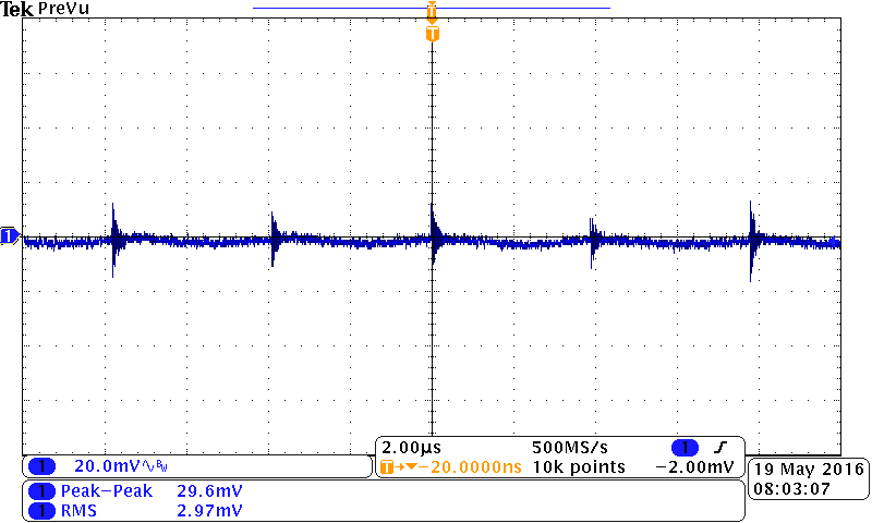
Output filters in the form of L-C networks are commonly used to reduce the level of switching noise or ripple from a DC-DC converter, see Figure 1 showing a typical converter such as in the MEJ series from Murata. However, the unfiltered level measured with an oscilloscope probe can be very misleading unless careful attention is paid to the measurement method. The ‘scope ground lead can easily pick up extra signal and common mode noise on the output can be seen by the instrument as differential mode. Common mode noise is signal from the outputs with respect to the environment ground and differential mode is signal across the DC output lines. It is this noise that the following circuitry ‘sees’ directly and may need most attenuation. For the filter design, the inductor should be chosen to not saturate at the maximum load current and to have just enough inductance to achieve the attenuation required. Remember that at the ‘rated’ current of an inductor inductance may have dropped considerably so a good margin should be incorporated. Load current steps through the inductance cause voltage transients according to E = -Ldi/dt so unnecessarily large values of L should be avoided. The DC resistance of the inductor should be low enough so as not to drop excessive voltage at the maximum load current. The mechanical style of the inductor can be important; low cost, open types such as drum cores can form the primary or secondary of a loosely coupled transformer with other circuitry inducing or picking up noise. If a drum or bobbin style is chosen, the part will have a winding ‘start’ pin which should be connected to the DC-DC output to provide some electrostatic shielding of this noisy node by the outer layers of winding. The self-resonant frequency of the inductor alone should be high, beyond which its impedance starts to reduce, allowing high frequency noise to pass through. The capacitor C is often present anyway in the system circuitry but ideally should be placed close to the inductor and DC-DC output and should be a low ESR type. Values are chosen for practicality but 10 – 100 µH for the inductor and 10 – 100 µF for the capacitor would be typical. The DC-DC data sheet should be consulted for any maximum value of output capacitance allowed. The self-resonant frequency of the combination of L and C will be typically much lower than the DC-DC switching frequency and would not normally present a ‘ringing’ problem especially as the circuit is damped by the load resistance. If the DC-DC converter has remote sense connections, beware connecting them on the load side of a noise filter to try to compensate for the voltage drop across the inductor. The filter would now be within the DC-DC control loop and adds phase delay, risking instability. Figure 2 shows the output noise performance of a DC-DC from a Murata Power Solutions converter with and without its data sheet recommended filter.
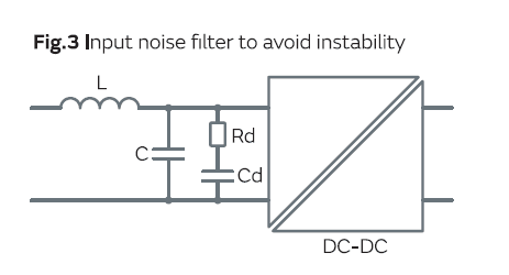
Input filters for DC-DC converters have additional considerations and are often designed to provide common mode as well as differential mode noise attenuation. Differential noise is typically specified in DC-DC data sheets as an RMS or peak-to-peak current through a defined inductance as the voltage observed depends on the source impedance which, unlike the load, is unknown to the DC-DC manufacturer. LC filters are again commonly used with the same considerations of inductor saturation, DC resistance and capacitor ESR. The output impedance and self-resonance of this filter can however be critical. If it is incorrectly designed, the filter can interact with the negative input impedance of regulated DC-DC converter such as the Murata NCM/NCS/NDS series to produce continuous oscillation. Why is the dynamic impedance of a regulated DC-DC converter negative? For constant load power and converter efficiency, the input power is constant implying that if input voltage increases for example, current decreases to maintain the constant power, representing the effect of a negative resistance. To avoid the oscillation, the input impedance of the DC-DC should be much higher than the output impedance of the filter which should also be damped so that at resonance its impedance does not rise close to the DC-DC input value. Damping can be achieved in different ways but an effective method involves an additional capacitor Cd and resistor Rd in series placed across the input as shown in Figure 3. Detailed component value selection can be found from the literature, starting with Middlebrook. (1) Again, excessively large values for L and C can be counterproductive; large inductors can have lower self-resonant frequencies spoiling attenuation in the MHz region. Large capacitors add to inrush current perhaps giving problems to the upstream power source. Sometimes the function of the filter can be more subtle, for example when paralleling DC-DC converter inputs, Murata Power Solutions recommends differential mode filters to prevent noise coupling between the converters causing potential reliability problems.
Designs often have to control the common mode conducted noise generated by DC-DC converters. There are standards for the allowed limits of this type of noise such as EN55022 but technically only relevant to AC-DC converters in information technology equipment. However the standards are often applied to DC-DCs as well. The limits are in the range of hundreds of microvolts across a 50 ohm load in a standard Line Impedance Stabiliser Network (LISN) up to 30 MHz so filters can be difficult to design - stray impedances and second order effects in lumped components have to be considered. There may also be safety considerations; if the input of the DC-DC converter is referenced to line voltage, safety standards limit the allowable leakage current to ground at line frequency, effectively limiting any capacitor value from the DC-DC input to ground and obliging it to be a safety type, typically ‘Y’ rated at the line voltage. The measured value of mode noise by the LISN is affected by differential and common mode noise. Even with no common mode noise, the standard test set up with a LISN will output half the value of the residual differential mode noise so filter networks that attenuate both types of noise should be used. Components don’t have to be ‘lumped’ however; common mode chokes can be designed with deliberately loose coupling, effectively adding series mode inductance so that just one inductive component can be used.
Typical types of inductor used for series mode noise suppression are iron powder toroids or drum cores such as the Murata 17/18/19/2200 series which are low cost and suitable for high current with low inductance. Common mode noise chokes such as the Murata 5000 series are usually high permeability ferrite types in the form of toroids or E-cores. Because in the circuit the two windings are in antiphase, flux cancels for the normal, circulating operating current so high turns and inductances can be used with little risk of core saturation while giving very high impedance to common mode noise. A comprehensive filter for differential and common mode input noise for a DC-DC converter could take the form of Figure 4 but all elements would rarely be necessary.
REFERENCES
(1) R. D. Middlebrook, "Design Techniques for Preventing Input Filter Oscillations in Switched-Mode Regulators," Proceedings of the Fifth National Solid-State Power Conversion Conference, Powercon 5, pp. A3-1 through A3-16, May 1978.
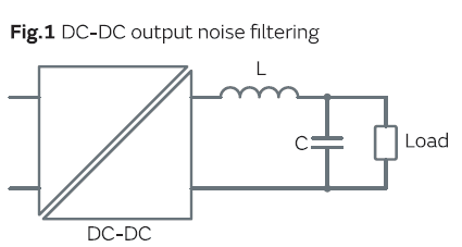
Fig2 without filter
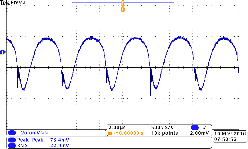
Fig2 with filter