AX-SIGFOX: Sigfox® Compliant Reference Design
Follow article
 Dave from DesignSpark
How do you feel about this article? Help us to provide better content for you.
Dave from DesignSpark
Thank you! Your feedback has been received.
Dave from DesignSpark
There was a problem submitting your feedback, please try again later.
Dave from DesignSpark
What do you think of this article?
What is Sigfox?
In the Internet of Things, the domain of nationwide coverage and ultra−low power consumption for smallest amounts of data cannot be addressed by established standards such as GPRS or LTE. This void is now filled by Sigfox, the ultra−low power cellular connectivity solution. It combines a low cost and simple approach together with ultra−low power consumption.
About the Chips
The onsemi SIGFOX chip is available in two versions: AX−SFEU and AX−SFEU−API. The chips add Sigfox functionality for up−link and down−link to any existing system at the cost of 20 × 13 PCB area. They can also be used as single chip solutions that control small sensor nodes. The AX-SFEU device is fully programmed for immediate operation as a Sigfox node, while the AX−SFEU chip addresses applications where the user wants to add additional software or wants control over the whole MCU.
About AX−SFEU
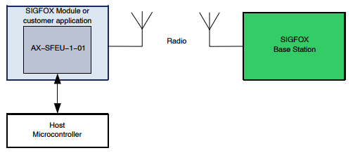
AX−SFEU is delivered fully ready and contains all the necessary firmware to transmit and receive data from the SIGFOX network. It connects to the customer product using a logic level RS232 UART. AT Commands are used to send frames and configure radio parameters. The commands adhere to SIGFOX AT Command Specification 0.7 (PRS−UNBT_AT_CMD).
AX−SFEU is already SIGFOX ready certified for end products. If the reference design and the Bill of Materials are followed exactly, no other certification from SIGFOX is required. EN300220 compliance checking is required.
About AX−SFEU−API
AX−SFEU−API is not delivered with any firmware. The Sigfox protocol library needs to be purchased. This version is ideal for customers who do not want another microcontroller in their product, but instead want to implement product functionality on the AX−SFEU−API chip. AX−SFEU−API is SIGFOX ready certified for end products. If the reference design, Bill of Materials and AX−SFEU documentation are followed exactly, no other certification from SIGFOX is required. EN300220 compliance checking is required. The API of the library corresponds to the SIGFOX API.

Design Layout
The layout is 20 mm × 13 mm. The antenna output is on the left side of the board. A 50 Ω antenna with a center frequency of 869 MHz must be connected. The connection to the host microcontroller and the power supply is located on the right side of the board. The module must be supplied with a DC voltage in the range of 1.8 V to 3.6 V as specified in the datasheet. A peak current of 50 mA during transmit at maximum power must be provided. Several test points for additional signals are available in the reference design. The chip supports up to 4 status LEDs for radio activity, CPU activity, transmit and receive. LEDs must be connected to ground via a series resistor (around 220 Ω). There are also 10 GPIO signals that can be queried and set using AT commands.
Click here for AX-SFEU-1-01-TB05, RF Transceiver RS (915-8757)
Click here for AX-SIGFOX SoC Development Kit RS (914-4301)