Operational Amplifier Equations For Circuit Design
Follow article
 Dave from DesignSpark
How do you feel about this article? Help us to provide better content for you.
Dave from DesignSpark
Thank you! Your feedback has been received.
Dave from DesignSpark
There was a problem submitting your feedback, please try again later.
Dave from DesignSpark
What do you think of this article?
Introduction
An operational amplifier (op-amp) is an analogue circuit block that takes a differential voltage input and produces a single-ended voltage output. How to solve op-amp circuits? Look at the following op-amp equations by several main operational amplifier applications circuit.
An operational amplifier has two input pins and one output pin. Its applications in a host of different circuits where their attributes of gain, input impedance, output impedance, differential input and so on. The major op-amp formulas used to calculate are shown as follow:

Fig 1. Voltage Follower
Note: Buffer High Impedance Signal and Low Impedance Load

Fig 2. In-phase Op-Amp
Note: In-phase Signal Amplification
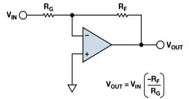
Fig 3. Reversed-phase Op-Amp
Note: Amplify and Invert Input
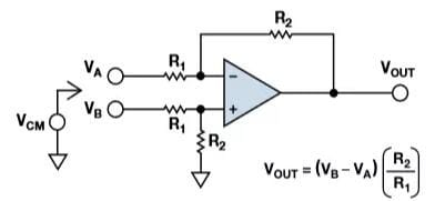
Fig 4. Voltage Subtractor, Differential Amplifier
Note: Amplify the voltage difference and suppress the common-mode voltage

Fig 5. Voltage Adder
Note: Summation of Adding Voltage Values

Fig 6. Low-pass Filter, Integrator
Note: Limit Signal Bandwidth

Fig 7. High-pass Filter, Differentiator
Note: Eliminate DC, Amplify AC Signal

Fig 8. Differential Amplifier
Note: Drive Differential Signal to Analog-to-Digital Converter From A Differential or Single-ended Signal Source
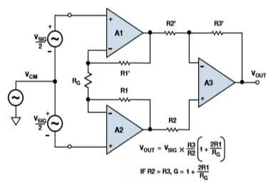
Fig 9. Instrumentation Amplifier
Note: Amplify the Low-Level Difference Signal and Suppress the Common Mode Signal

Fig 10. Single-State Op-Amp Noise
Note:
RTO NOISE=NG×RTI NOISE
RTI=Converted to the Input
RTO=Converted to the Output

Decibel Formula (equivalent impedance)

Johnson-Nyquist Noise Formula

Ohm's Law (DC circuit)

Fig 11. Closed-loop Frequency Response (voltage feedback amplifier)

Resistance Formulas

Reactance Formulas
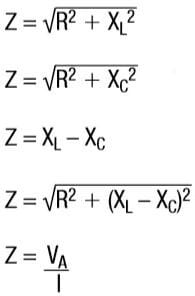
Impedance Formulas (in series)
Note:
RL in series
RC in series
LC in series
RLC in series

Voltage and Impedance Formulas (parallel connection)
Calculation Tool: Apogeeweb Free Tool provides a one-stop resource that can meet your needs for various electronics industry calculations, and will show the illustrated results for you immediately.