Designing a modular synthesiser Part 2: Making basic noise
Follow article Dave from DesignSpark
How do you feel about this article? Help us to provide better content for you.
Dave from DesignSpark
Thank you! Your feedback has been received.
Dave from DesignSpark
There was a problem submitting your feedback, please try again later.
Dave from DesignSpark
What do you think of this article?
Next steps
In the first part of the synthesiser series, which can be found here, we looked at getting started with designing a 40106 oscillator. Currently, our oscillator isn't very musical as we left it in a fixed frequency position. Really our only option for altering the pitch at this moment is to change the capacitance of C1 in figure 1. Physically plugging and unplugging a new capacitor value isn't very practical so let's look at adding some basic control voltage, you may know it as CV, and while we are at it let's add an op-amp buffer to the circuit to allow correct playback.

Figure 1. Fixed frequency sawtooth wave. Where we left off in Part 1.
Power supply
Something I glossed over in the first part was how are we powering the circuit? The simple answer is a 12v dual power supply. While the ICs used in this series can be powered with a lower voltage, 12v +/- is standard on Eurorack modules and the plan is to install this module into a Eurorack setup down the line. While I built my own power supply it is possible to get them off the shelf, for more information take a look at this buying guide. In the article, Modular Grid is mentioned, which allows you to plan your modular synthesiser and calculate your power consumption, a very useful tool.
Op-Amps
In the previous post, we mentioned how connecting the oscillator at this stage would interrupt the oscillation, due to improper impedance matching between the oscillator's output and the speaker's input. The most viable place to connect would be R1 in figure 1, however, this provided the signal with another path to ground and the output would not be audible due to the subsequent voltage drop. To prevent loss of signal we are going to use a non-inverting voltage follower. We are going to use the TL074 Op-Amp (709-2380)

Figure 2. Non-inverting voltage follower.
A perfect voltage follower should provide us with an amplifier gain of 1. This does not offer an extra amplification of the signal, its task is to balance the impedance of the input signal to the output source's impedance. The op-amp works by differentiating the voltage levels at its two inputs and multiplying the difference by the op-amps given gain value, the maximum voltage output is determined by the supply voltage. In this case, the op-amp is utilizing negative feedback voltage as explained below.
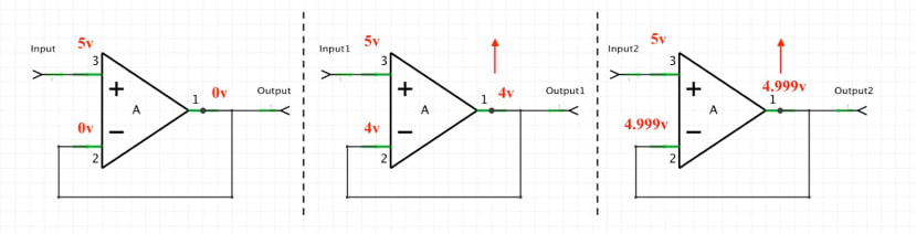
Figure 3. Showing the operation of a negative feedback buffer, and how over time the voltage level at its output matches its input.
The buffer’s non-inverting input (Pin 3) probes a voltage, let's say for example 5 volts, while the inverting input Pin 2 connects directly to the output Pin 1, creating the negative feedback loop. Before the op-amp calculates the gain it will switch its output to 0v, meaning the inverting input and output start at the same voltage level. The difference between the inverting input and non-inverting input is then multiplied by the gain factor, increasing the output level. Since the inverting input is connected to the output this, in turn, increases the voltage. The differences between the two inputs begin to decrease, eventually meaning the output stabilizes slightly below the non-inverting input1, Creating a unity gain close to one. This process loops forever, keeping the voltage stable through negative feedback.
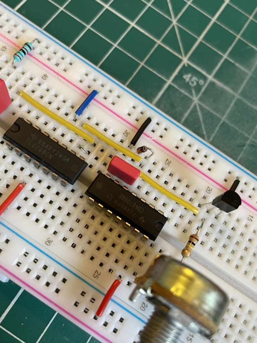
Figure 4. Op-Amp patched on breadboard.
Audio oscillators produce Alternating Current as it oscillates across a zero crossing. To properly patch the signal into a listening source an AC coupling circuit needs to be added to remove unwanted DC offset. DC components happen in the positive range, with the help of a capacitor the signal can be offset to be more audio friendly2. Just like a speaker cone it needs to push forwards and backwards to vibrate, without AC coupling the speaker would just push forward, causing unwanted clicks3.

Figure 5. Schematic showing Hex Schmitt trigger, Non-inverting voltage follower, AC Coupling, Control voltage.
Basic CV
Adding voltage control to the circuit is relatively simple. The best option for changing pitch is to change the resistance value, to which we have many options such as an LDR or a potentiometer, however, the classic solution is to use a transistor. In this case, we are going to use a BC548 NPN Bipolar Junction Transistor. Read a little more about NPN transistors here and BJT transistors here
To do this we must first replace the drain resistor, by connecting the collector at the junction of the capacitor, diode and Schmitt trigger, while the emitter connects directly to the ground. By varying the voltage at the base of the NPN transistor, using a variable voltage divider, we can change the speed at which the capacitor drains through the emitter, varying the pitch. It is important to add a resistor in series with the potentiometer, this will protect the transistor in case the pot is opened completely, supply the transistor with 12v from the power supply.
This is a very basic implementation, and if you have been following along you may notice the pitch is only affected by a tiny voltage range, and it is quite hard to control. This is due to scaling and offset issues that we will correct in the next instalment. We will also look at improving the stability of the instrument, currently, ambient temperature is affecting the tuning.
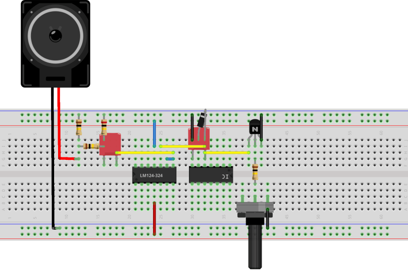
Figure 6. Breadboard diagram
Parts list:
- R1/ R2 - 10k resistor (707-7745)
- C1 - 2.2nf Polyester capacitor (122-4241)
- C2 - 1uf Polyester capacitor (108-2592)
- D1 - 1N4148 diode (739-0290)
- TL074 Op-Amp (197-7553)
- 40106 IC (044-2943)
- Breadboard (203-4623)
- Jumpers (791-6463)
References:
Blake Jacquot. “AC Coupling.” YouTube, uploaded by Blake Jacquot, 2 July 2012,
www.youtube.com/watch?v=SsSlbno9G44.
Marty. “How Do Speakers Work? A Speaker Guide For Everyone – With Diagrams.” Sound Certified, SoundCertified.com, 6 May 2021, soundcertified.com/how-do-speakers-
work
Robbins, Michael. “Op-Amp Voltage Buffer Chapter 7.2.” Ultimate Electronics Book, 30 July 2020, https://ultimateelectronicsbook.com/op-amp-voltage-buffer/