Create a custom PCB Board: Part 2 - Mounting Holes
Follow tutorial
 Dave from DesignSpark
How do you feel about this tutorial? Help us to provide better content for you.
Dave from DesignSpark
Thank you! Your feedback has been received.
Dave from DesignSpark
There was a problem submitting your feedback, please try again later.
Dave from DesignSpark
What do you think of this tutorial?
This tutorial requires:
DesignSpark PCB V11.0.0With our board outline complete we now continue with the design and add mounting holes. Mounting holes are pads without a copper ring and without any plating, just a simple drilled hole.
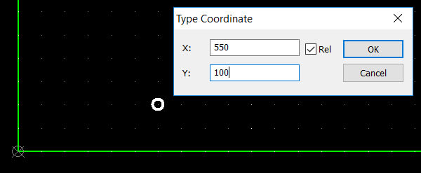
Select the icon to add a pad and before placing use the short cut key "=" to launch the Coordinates window. From the drawing (see part 1) enter the X and Y coordinates of the hole and click OK to position it.
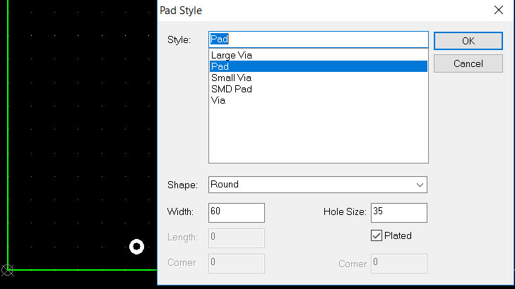
While the pad is highlighted use the short cut key "S" to edit the "Pad Style". (Or use the normal right click menu method). This window shows the settings for the default pad which we now edit to create our required hole.
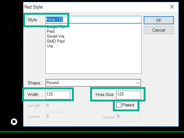
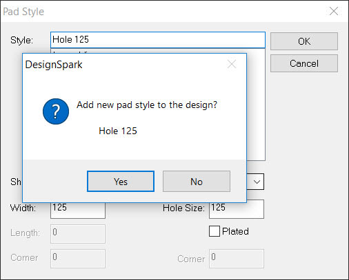
The image shows the entries highlighted to edit. Male the "Hole Size" and (pad) "Width" 125mils asper the drawing. Uncheck the "plated" box and enter a useful name, here we use "Hole 125" to show the size and the fact it is a hole.
Clicking "OK" will now present a warning as the hole and width are the same size, but as this is as required click OK.
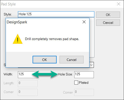
A second window opens asking us to confirm we wish to create a new pad style in the design, again click "Yes" as this is required.
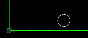
Our first hole is now defined and positioned.
Creating and positioning further holes is now simple as they are defined as a Pad Style. Also we can use copy and paste to speed up the process.
With hole selected press CTRL+C to copy and CTRL+V to paste, the pad will be highlighted i.e. select so press the shortcut "=" and type in the next hole coordinates and click OK to place.
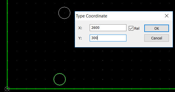
To place the remaining two holes, press CTRL+V to paste a hole and "=" to enter the coordinates for each position.
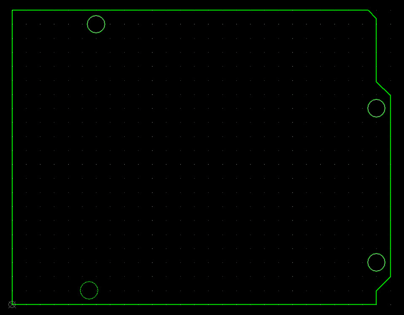
The PCB board outline with mounting holes is now complete.
In part 3 we show how to add details of where connectors can be positioned on the shield and notes to avoid the USB and Power connectors on the main Arduino Uno R3 board.