Connectivity on the board
Follow articleHow do you feel about this article? Help us to provide better content for you.
Thank you! Your feedback has been received.
There was a problem submitting your feedback, please try again later.
What do you think of this article?
The printed circuit board (or PCB) is the true unsung hero of the electronics age. Before PCBs, electrical circuits had to be created with masses of wires in a point-to-point arrangement. If you try to imagine the electronics world of today without PCBs, you will start to understand the vital part that they have played in the modern world.
They are all-pervasive. There is hardly a piece of electrical equipment in use today that does not use a printed circuit board. The simple fact that you are reading this on a screen means that there is at least one PCB within arms reach of you right now. In all likelihood, there are probably several.
Printed circuit board design is governed by many factors, but two of the most important are the size of the components on the board, and the need for the board to connect to the outside world. In fact, one has a direct impact on the other. As microprocessors grow smaller, the size of the connector used on the board becomes a larger and larger problem. 30 years ago, the DIN 41612 connector was king. A 96-pole DIN 41612 connector was over 80mm long, and stood well over 11mm tall. With technology like this, it is hard to image the slimline, hand-held designs of today's smartphone.
Therefore, connector manufacturers have had to constantly innovate in an attempt to keep pace with the relentless miniaturisation of the electronics world. This has also meant that the whole connection method has had to change. Back when DIN 41612 ruled the roost, many electronics systems used a backplane structure, with a number of daughterboards plugged in at right angles to a passive backplane which acted as little more than a data-transfer system. Needless to day, this sort of arrangement wouldn't work very well in today's miniature devices
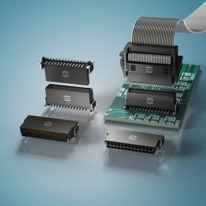
Fig 1. From left to right: Cable-to-Board; Extender Card; Mezzanine, Mother/Daughter Board
But even in today's world of single-board computers and tiny devices, there is a need for a versatile, compact connector system that allows two PCBs to be joined together in the most efficient way.
Our friends at HARTING have created a possible solution to all of these problems with the har-flex® series of connectors, which has been developed as a universally compatible board-to-board connector family. This product series is available in straight and angled versions, in addition to the cable mounted connectors with ribbon cable termination utilizing IDC technology. Advantages include the flexible spacing of vertically and horizontally arranged PCBs, allowing a number of PCBs to be connected to a BUS or for multiple board connection.
The har-flex® connector family, available with even number contact counts of between 6 and 100, use a compact 1.27 mm pitch. This design has already proved its mechanical stability within industrial applications and is able to handle high data rates. They are available fully surface-mount (SMT) compliant or can be supplied with through-hole (THR) hold down frames for additional mechanical stability.
Download the har-flex catalogue today and see how it might solve your next PCB headache.


