Components with multiple footprints - why have them? How to add them.
Follow article
 Dave from DesignSpark
How do you feel about this article? Help us to provide better content for you.
Dave from DesignSpark
Thank you! Your feedback has been received.
Dave from DesignSpark
There was a problem submitting your feedback, please try again later.
Dave from DesignSpark
What do you think of this article?
DesignSpark PCB and Engineer subscription support the use of multiple PCB footprints for a single component.
But why would you want multiple footprints for a component?
An advantage of having additional footprints is that they can be tailored to the PCB requirements, such as having large pads for hand assembly or minimal pads for high-density PCB designs.
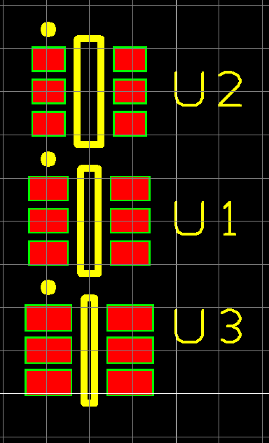
Many of the components from Ultra Librarian now come with three footprints as shown in the image above.
The DSL import currently only assigns one footprint to the component (this is being examined to automatically include all three footprint options), here we illustrate how to add the additional footprints that are downloaded.
Once these are added to the component, you will then have the option to decide at design time which footprint you require or at a later time by updating the component. So now let's understand the steps to add the available footprints from an UltraLibrarian download.
For this example, we select the Texas Instruments LM3880MF-1AE/NOPB RS (761-5110)
From the Ultra Librarian site search on LM3880MF-1AE/NOPB, which is also available from this download link
https://app.ultralibrarian.com/Search?queryText=LM3880MF-1AE%2FNOPB
As you will observe there are three footprint size options available. All three will be included in the DSL file and extracted into the library.

If you are familiar with DSL component importing, jump to the section "Let's add multiple footprints!"
Download the component and then unzip it, next import the Schematic Symbol, PCB Symbol and Component as normal which is detailed here.
A quick visual summary of the simple steps follows for DSPCB.
Note users with Engineer plan can use "drag and drop" in place of the "Add File" steps.
Import the schematic symbol.

Similarly for the PCB Symbol.

NOTE the three PCB footprints that are now available.
Finally, import the Component to the library.

The component is now ready to use, but at this point has a single PCB symbol, in this case, DBV0006A_L
We shall now illustrate how to add the two other available footprints DBV0006A_M and DBV0006A_N
Let's add multiple footprints!
First, a big thanks to Brad Levy for his detailed description posted on the forum.
Here we illustrate the steps.
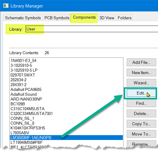
1. In the Library Manager - Components tab, select the component and click the <Edit> button.
2. The standard component editor window now launches.
Close the "Properties" window and now click the "Add Package" icon on the toolbar or use the menubar.
Select the package you wish to add, provide a Package description in the top box, this is normally the basic footprint description such as "SOT-23", but here we keep the UltraLibrarian description for convenience. Now click <Add>.

3. The new footprint is added and now requires the pins to be mapped. As UltraLibrarian created the pin mapping as 1:1 (as shown above) this can be used. Edit the pin mapping if you require anything different.

4. Save the new component from the "Save" icon or File - Save. Use the current Component Name and "Yes" to overwrite to update the component to have the additional footprint.
NOTE. You may also wish to set the default footprint which will be used when using "Add Component".
See the section below "Set which footprint is the default", however, this can be done at any stage after the component is created.

You may now inspect the component in the Library Manager and will observe the additional footprint now available.

Repeating for the third available PCB footprint we have a usable component where the pad size of the footprint can be selected at design time.
From "Add Component", you can now select the package required for your design.

You may select and use all the available component footprints as required for your design, you are not restricted to just one.
You may also change the footprint, by selecting the schematic symbol (highlight) and from "Properties" select <Change> and select the new required footprint.
Set which footprint is the default.
Now that you have multiple footprints to select from you may wish to set which footprint is set as the default when adding the component rather than having to select each time.
Simply follow these steps.
In the Component editor right-click and select "Edit Packages". You will now see the available packages with a "C" and "D" identifying the Current and Default packages.
Select the package that you wish to have as the default and click <Make Default>
You will notice the "D" has moved to identify the default package. Click <OK>

and when the component is next used in your design that will be the default package assigned.

Similarly, when the component is open in the Component Editor you can from the right-click option select "Edit Package", then select a package, click <Make Current> for that editing session.