What outputs can I use with my Raspberry Pi? Part 2 - Loads larger than an LED
Follow article
 Dave from DesignSpark
How do you feel about this article? Help us to provide better content for you.
Dave from DesignSpark
Thank you! Your feedback has been received.
Dave from DesignSpark
There was a problem submitting your feedback, please try again later.
Dave from DesignSpark
What do you think of this article?
This article was written by James Macfarlane and Lucy Rogers
Loads larger than an LED
In Part One of this series on outputs, we looked at LED's and using a Raspberry Pi to control and power them.
In this article, we will look at loads larger than an LED. (Part three - coming soon - will look at motors).
To control loads much larger than an LED, we need a driver circuit that allows the small signal from the GPIO pins to control the larger current (and voltage) that bigger loads require.
Possibly the simplest driver circuit is the open collector driver - we’ll go into a little more detail in a moment - but here's one we made earlier, for interest.
Open collector drivers can be built for a variety of power levels but if using a single transistor they will happily switch up to about an amp so will operate small motors, lamps, large LEDs (or arrays of LEDs) and relays (allowing even higher currents / voltages to be safely controlled.)
Open Collector Driver
An open collector driver uses a transistor. Transistors allow a small input current to control a bigger current. In Figure 1 we show an example of a Pi driving a 12V relay using an open collector driver.
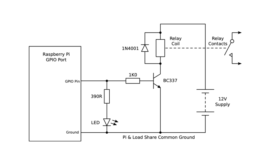
Figure 1: Open Collector Circuit Driving a 12V Relay from a GPIO Pin
When the GPIO pin is turned-on, the Pi supplies a small current to the base terminal of the transistor via a 1K resistor. The transistor then allows a much bigger current to flow into the collector terminal. In an open collector circuit, the emitter is the “common” terminal - both the base and collector currents flow out of it. This means that it doesn’t provide isolation, so you need to take care that the big load current does not end up flowing through the Pi. The laws of current flow take care of this for you if the load is running off a separate power supply. (See the section on ground loops in part four (coming soon) for more detail.)
The great thing about an open collector driver is we can choose any voltage and current we want for the load as long as they are within the maximum ratings of the transistor. This applies up to about an amp of load current. Above this, a different approach is needed. More on this shortly.
The diode (e.g. 1N4001 (628-8931) ) is required to protect the transistor. If the load has any kind of inductive coil in it, e.g. it is a relay or motor, when the transistor is turned off there will be a back-EMF - a large spike of voltage - produced by the collapsing magnetic field. This can be large enough to damage the transistor. The diode limits this back-EMF and therefore protects the transistor at turn-off. (For more details on this consult a good electronics book, such as The Art of Electronics).
The LED in the circuit is just for de-bugging, if it lights up then the transistor is getting a signal to turn it on.
Even Larger Currents
If you need a higher current than about an amp, a single transistor won’t have enough gain to allow the tiny 16mA signal from the Pi to fully turn-on the load and the transistor will get hot. One way around this is to use a Darlington pair (two transistors that act as a single high-gain transistor) but this has the slight disadvantage that there is a bigger voltage drop across the transistor when it’s on. Instead you could use a MOSFET (another type of transistor) and the circuit becomes known as an open drain output. Note, however, that many MOSFETS won’t fully turn-on when driven with a 3.3V signal and could overheat. To get around this, you either need to pick your MOSFET very carefully or use a level converter to drive it. You can buy add-on boards and HATs for the Pi that incorporate sophisticated driver chips which will allow much bigger loads to be controlled. More on this in part three (coming soon) when we get on to the subject of motors.
Relays
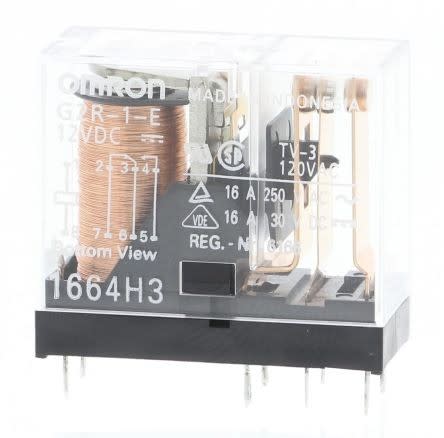
Figure 2: A SPDT PCB-Mounting Relay (036-6293) - (Image credit: RS Components)
Another way of controlling larger currents with the Pi is to use a relay. A relay is a switch operated by an electromagnet, rather than a human. A relay is made of two parts - the coil and the contacts. You can see these in Figure 2 - the coil is on the left, coloured orange. The contacts are the round “pips” at the top of the gold-coloured vertical bars on the right. A magnetic field is formed when a current flows through the coil. This pulls a lever that connects two or more contacts in a secondary circuit. When the coil is switched off, the contacts open again. This allows a relatively small electric current to control a much larger one.
The relay coil needs a slightly higher current than can be safely provided by the GPIO pins but our old friend the open collector driver comes to the rescue, as you saw in Figure 1. In this circuit, you can see the schematic symbol for the relay coil is a box, a bit larger than a resistor symbol. The symbol for the contacts is like that of a switch, but with a more “spiky” blob. The dotted line indicates the mechanical linkage between the coil and contacts, though this isn’t always shown.
Isolation
Relays have a nice property - the coil and the contacts inside the relay are electrically isolated from each other. This means they can take part in completely different circuits without the circuits affecting one another. This “galvanic isolation” property of relays makes them useful when you want a low-voltage circuit, such as a Raspberry Pi GPIO, to control a high-voltage circuit, such as one fed directly from the mains. (Designing and building circuits powered directly from the mains also requires other precautions which are beyond the scope of these articles.)
Relay Terminology
The terminals in a relay are called:
- Coil (Sometimes marked A1 and A2)
- COM (Common)
- NO (Normally Open)
- NC (Normally Closed)
When power is applied to the coil terminals, the relay contacts move to connect the COM terminal to the NO terminal. “Double-throw” or “changeover” relays have a third terminal (NC) which is connected to COM when the relay coil is not energised.
Some relays have more than one set of contacts. These are called multi-pole relays. Each “pole” behaves like a separate switch with its own COM, NO (and possibly NC) terminals. All the poles are controlled by one coil.
Relay contact configurations:
- SPST - Single Pole, Single Throw - just one set of normally open contacts.
- SPDT - Single Pole, Double Throw - one set of changeover contacts.
- DPST - Double Pole, Single Throw - as SPST but has a pair of normally open contacts
- DPDT - Double Pole, Double Throw - has two sets of changeover contacts. These can be used, for example, to reverse the polarity of a motor.
- 4PDT - Four Pole, Double Throw - has four sets of contacts, as above.
You may also see the initials CO (change-over) instead of DT - it means the same thing - e.g. DPCO is the same as DPDT. Similarly, the initials NO (normally open) are sometimes used instead of ST, e.g. SPNO is the same as SPST.
Relays are usually specified by two numbers - their coil voltage and the maximum current the contacts can switch. Note that the relay might have different ratings depending on whether the contacts are switching AC or DC - consult the manufacturer’s data for more information.
Relay coils are not normally polarity-sensitive - you can connect them either way around. However, this is not necessarily true for relays with very low voltage (e.g. 5V) coils. These sometimes have extra magnets inside to give the coil a helping hand, so the field needs to be in the right direction. This caught one of the authors out once, resulting in a PCB having to be re-made.
Solenoids
As we saw with relays, electromagnets can actuate switches. They can also operate other things. Solenoids are a kind of electromagnetic actuator that provides a small amount of linear movement. They are used to open doors and latches and to operate valves, levers and other mechanisms. They are also used in vending machines, pinball games, washing machines and car engines.
Solenoids consist of a coil of wire wrapped around a cylindrical tube. Free to move inside the tube is the armature, a rod of magnetically permeable metal, such as iron. When current passes through the coil, a magnetic field is produced. This magnetic field pulls the armature into the tube. When the current is stopped, a force, such as a spring, is required to make the armature go back to its original position. Solenoids can be design to either push or pull when energised. The distance the armature moves is called the stroke. Solenoids are usually designed to be on/off devices - they are either energised or not. Proportional solenoids do exist but are not so common.
There is a great four minute video explaining how solenoids work by Jeri Ellsworth
To control a solenoid from a Pi, you can generally just use an open collector driver connected to a GPIO pin. Just as with relays, you will need to put a diode across the solenoid to suppress the back-EMF.