Using DesignSpark Mechanical - Mini-Guides and Solutions
Follow article
 Dave from DesignSpark
How do you feel about this article? Help us to provide better content for you.
Dave from DesignSpark
Thank you! Your feedback has been received.
Dave from DesignSpark
There was a problem submitting your feedback, please try again later.
Dave from DesignSpark
What do you think of this article?
If you haven’t visited DSM Learning area you may be missing out on some valuable hints and tips. We have a whole heap of quick guides and tutorials, many created by users of our software, to help you get the most from DesignSpark Mechanical.
What you can find:
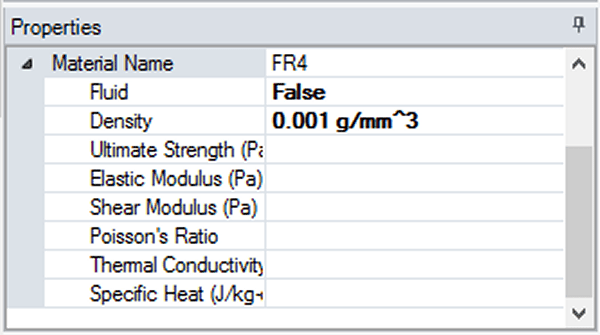
Adding Material Properties
DesignSpark Mechanical allows you to specify the material properties for the solid objects in your assembly. There is a local library of commonly used industrial & production grade materials.
You can also add a new material to your local library. You will need to list certain physical properties to define the material.
These can be entered in the properties tab.
Example 1: For FR-4 (fire retardant composite material for laminating PCBs), the values can be found here: https://en.wikipedia.org/wiki/FR-4
Example 2 (copper): Depending on the grade of copper you are using, there is one pre-populated in the local library (OFE grade - high electrical conductivity). Just drop-down the material name list to find more.

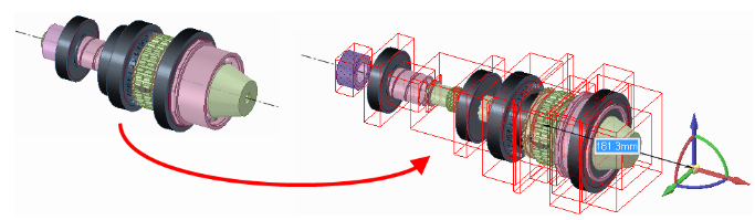
Exploding an assembly
- Select all the components in the Structure tree that are part of the assembly you want to explode.
2. Anchor the Move handle on one component.
3. Select the Fulcrum tool guide and click another component.
4. Select an axis on the Move handle and drag to explode the assembly in that direction.
How do I create a simple cone?
To create a simple cone you need to start off by drawing a circle with the diameter of one end of the cone. Draw the bottom of the cone.
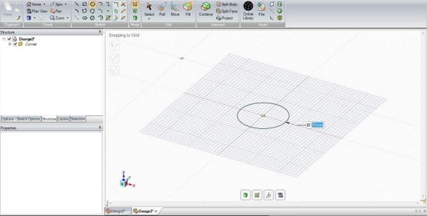
Pull (P) the Circle to the height of the cone required

With the Pull tool selected, select the edge of the diameter to be reduced.
A Single Click on the diameter will also bring up the quick menu as shown below.
Select the "Pivot Edge" tool which will change the pull arrow to show two arrows (radial and axial).

Select the radial arrow and pull to the new diameter.

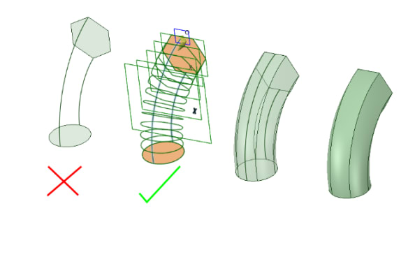
Can I blend from one shape to another?
This question has been asked many times and there are several ways to do this.
One of our users had the answer:
- Draw your two different shapes
- Draw two lines to connect the two surfaces
- Select both surfaces
- Use the 'Pull' tool with the 'Sweep' option. Control-click selects the two lines as the sweep profile, then press Enter
- Three surfaces will be created
- Select the three surfaces and join together using the 'Combine' tool
- One Solid created
- Delete the curves

There is an ever-growing repository of hints and tips that can be found in DSM Learning area.