Thingatron
Follow article
 Dave from DesignSpark
How do you feel about this article? Help us to provide better content for you.
Dave from DesignSpark
Thank you! Your feedback has been received.
Dave from DesignSpark
There was a problem submitting your feedback, please try again later.
Dave from DesignSpark
What do you think of this article?
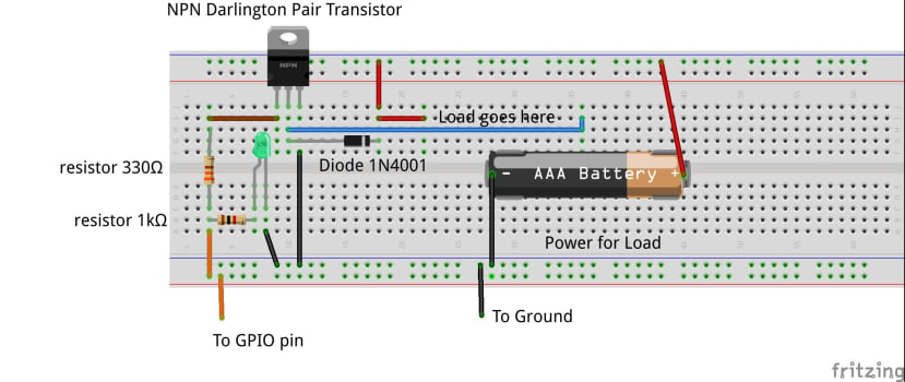
The General Purpose Input/Output (GPIO) ports on development and microprocessor boards generally only work with logic level signals. This means they can only supply 3.3v and a few mA of current from each pin. This is enough to power an LED but to control a more powerful load (like motors) some additional circuitry to boost the current and/or voltage to a higher level is required.
One way to do this is to use an open collector driver. This is an electronic circuit that uses a transistor – that is turned on by a logic level signal from a GPIO port to its base terminal. The transistor can then switch a much bigger current via its collector terminal. This big current flows back to a separate power supply. An open collector driver can switch any voltage and current for the load so long as it is within the rating of the transistor.
The Open Collector driver, with an indicator LED, can be made on a breadboard, as in the picture diagram.
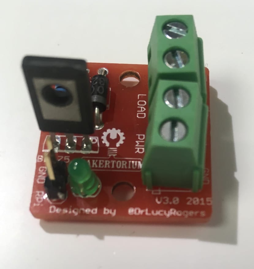
The Thingatron
As I need them a lot, I designed a PCB and have called it a Thingatron. It has screw terminals for the power and the load.
Related articles
This Thingatron mini project is provided as an addition to my WineTime project. See the related 'Battery Switch' mini-project too: