Student Innovation - Exploring Thermoelectric Cooling
Follow article Dave from DesignSpark
How do you feel about this article? Help us to provide better content for you.
Dave from DesignSpark
Thank you! Your feedback has been received.
Dave from DesignSpark
There was a problem submitting your feedback, please try again later.
Dave from DesignSpark
What do you think of this article?
This article is a summary of the rabbit hole I fell into whilst investigating a new application of the Thermoelectric effect. I’m an engineering student about to start the final year of my course, specialising in electronics. I particularly enjoy finding simple and integrated engineering solutions to problems; one such problem came from a family member, struggling with their own home fermentation project.
Fermentation is a widely used food preparation method for products such as wine, beer, yogurt, bread, sauerkraut and many more. It relies on the conversion of sugars and other carbohydrates into carbon dioxide and alcohol or preservative organic acids by yeasts and bacteria. The bacteria can also increase the health of your gut microbiome and digestive system, enhancing the immune system. Kefir, Miso, Kimchi and Kombucha are just a few examples of such “Probiotic Powerhouses” - fermented products packed with a wide variety of bacteria, yeast, vitamins, and minerals with measurable (although sometimes contested) health benefits. My relative swears by the improvements they have experienced by replacing milk with Kefir on their breakfast cereal.
Although breakfast is at (roughly) the same time every day, the rate at which the bacteria in Kefir break down the lactic acid in milk varies significantly with temperature. This means that the time taken for Kefir to reach the correct point in the fermentation process can vary by hours depending, for example, on whether it’s a cold winter’s day or a hot summer’s one. This is where I was called on to “do some engineering” and create a temperature-stable environment for the fermenting process to ensure that variations in ambient temperature didn’t have an effect.
For fermented products (e.g. bread and yoghurt), which prefer a temperature well above ambient, the problem is already solved. Proving drawers and Instant pots use a resistive heating element and a thermostat to regulate temperature. However, in the case of kefir, experimentation by my relative found that a temperature of around 18°C produced reliably good results within a convenient timespan (24 hours). Where I live, this could be above or below ambient temperatures in the house, depending on the season. A resistive heater would work in the winter but would be useless in the summer when high temperatures cause the kefir to ‘split’ ruining the taste. I needed a solution capable of seamlessly switching between heating and cooling. After some searching, I came across the Peltier Heat Pump.
Peltier Heat Pumps rely on the Thermoelectric effect – a reversible process where heat energy can be transported by charge carriers. This effect is used in devices such as thermocouples to measure temperature, where a thermal gradient produces a current that flows through the junction of two dissimilar metals. In a Peltier Heat Pump, current is passed through a series of alternating n-doped and p-doped semiconductors, connected by metal conductors. The net movement of charge carriers transports heat energy across the device, leading to a temperature difference between two of its faces. If the current direction is swapped, heat energy travels in the other direction. These devices are widely used in temperature control applications such as in lasers, where a stable temperature is required for high output power and output wavelength stability. On the consumer side, Peltier Heat Pumps are used in mini fridges as a cheap, solid state alternative to traditional vapor-compression cycle refrigerators.

Thermoelectric Cooler Diagram
One widely available Peltier module is the TEC1-12706. This has 127 pairs of n-doped and p-doped pellets, in a 40x40mm arrangement between two ceramic plates. Datasheets claim that the module is capable of 6A of current at 12V and a temperature difference between its faces of over 60°C, but they are very rarely used at these extremes. This is because the module creates its own heat from electrical heating in the same way that a resistive heater would. At full power, 72 watts of the module’s self-created heat would have to be removed from the system by a heatsink, as well as the heat being transported from the cold side.
For an initial prototype, I removed the Peltier module and heatsinks from an electrical camping cool box and mounted them to a polystyrene enclosure. I connected the heat pump to a simple thermostat circuit (see below) powered from a 5V USB adapter. The desired temperature could be set with a potentiometer, but the setup had no ability to cool, only the ability to heat if the environment were too cold. During the winter, the time to correct fermentation of the kefir was more consistent, which was especially noticeable over cold nights, when kefir left out in the open would take several more hours to ferment. However, the polystyrene box was excessively large for a 500ml glass jar of Kefir, did not work at all in the summer and was overly sensitive to adjustments to the potentiometer, meaning dialling in the correct temperature was difficult.

Initial Prototype Circuit

Initial Prototype
My second prototype aimed to fix all these problems. Using a 3D printed enclosure, the main heat pump stack consisted of an aluminium plate for the Kefir jar to sit on. Underneath this, the Peltier module is sandwiched between the plate and a heatsink, with a fan to blow air upwards onto the fins to remove excess heat. A door allows access into the enclosure to place the jar. The heart of the electronics is an ARM Cortex M0+ microcontroller, which is used in Arduino boards such as the Adafruit Trinket M0. This interfaces with a rotary encoder and OLED screen for user input and feedback, a MAX30205 temperature sensor with a 0.003°C resolution (designed for human body temperature sensing in wearables) and an H Bridge IC for bidirectional current flow through the Peltier Module. The fan, in series with a diode, is connected in parallel with the Peltier module so that when the pump is cooling, the fan will run to remove heat from the heatsink. A PID library was used to determine the current direction and amount of time in a 10 second period that the Peltier module should be on for.
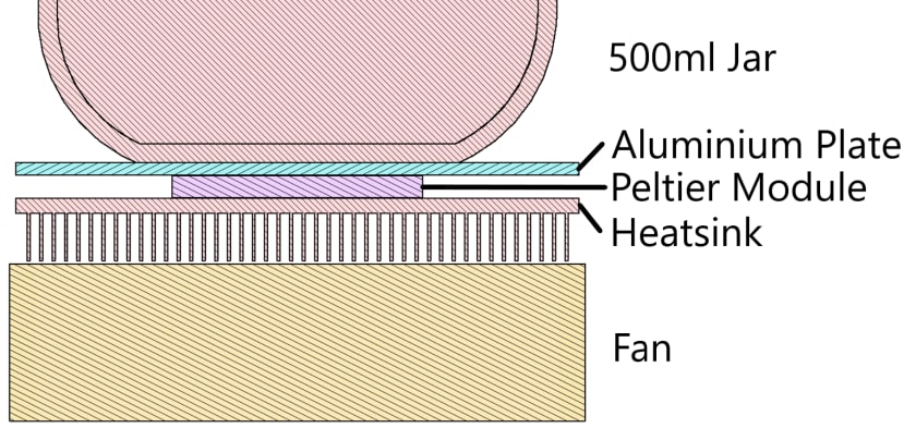
Overall Heat Pump Design

Second Prototype Drive Circuit
The smaller size was much appreciated, and the improved user input enabled the desired temperature to be selected in increments of 0.1°C. This prototype has been running continuously for 10 months, generating useful feedback on some problems with this design. Firstly, the 10 second control windows for the Peltier module and Fan meant that when cooling, the fan would be constantly turning on and off, which was annoying to listen to. Secondly, although the circuit design had the ability to cool the enclosure, the limited power supplied by the 5V USB adapter meant that the lowest temperature reachable was around 3°C below ambient. The final problem was the general thermal design of the enclosure. The combination of bad thermal conduction between the aluminium plate and the glass jar and the bad insulation properties of the 3D printed enclosure result in the contents of the jar failing to uniformly reach the desired temperature, particularly a problem when the ambient temperature is low. Although the Peltier module is set to heat, only the bottom third of the jar approaches the desired temperature, meaning while fermentation is achieved in the lower part, it is not towards the top of the jar.

Second Prototype
Over the last year I have been working on a third design, which I hope to turn into a marketable product. I am again aiming to fix the deficiencies in the previous prototypes and simplify the design, reduce BoM cost, and make a more easily manufacturable product. I’ve added an aluminium tube to surround the jar (to help with temperature uniformity) surrounded by 32mm thick nitrile rubber foam insulation. The fan size has been increased and is now independently controlled with a dedicated MOSFET. The biggest change is to the main Peltier drive circuit, which I aim to run off a 12V 2A adapter. This more than quadruples the available power to the heat pump, meaning the enclosure should be able to cool to around 15°C below ambient temperature and heat up to 50°C. This significantly widens the range of fermentation products that can benefit from a temperature-controlled environment. The Peltier module can’t be run directly from 12V without exceeding the current capability of the supply, so I used my recently gained knowledge of switch-mode power supplies to design a bipolar buck converter, essentially adding a second order filter to the output of the H bridge, and controlling it using high frequency PWM.
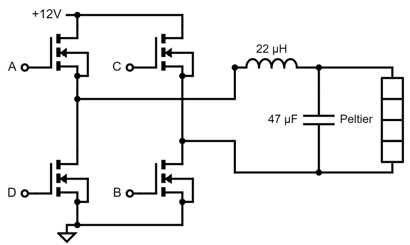
Third Prototype Drive Circuit
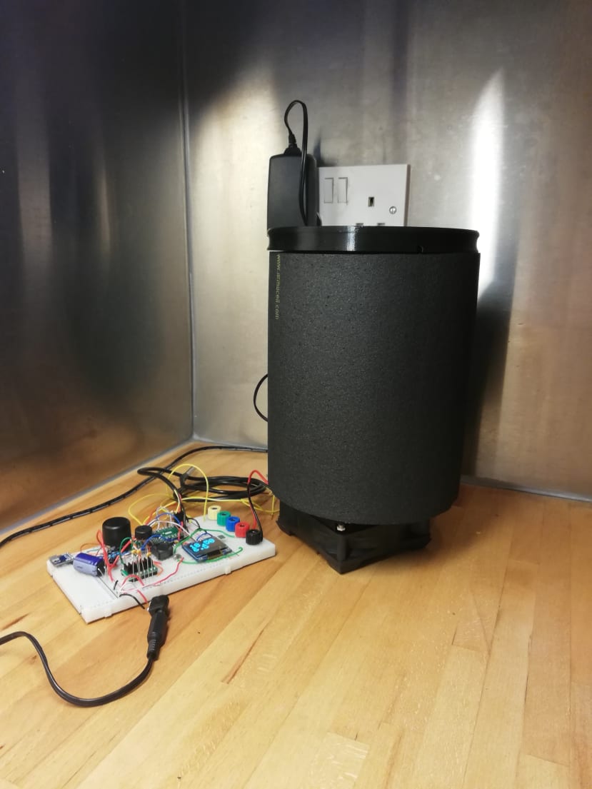
Third Prototype in Progress
Initial testing is positive to the extent that, despite the inevitable temperamental qualities of a prototype, it’s been stolen a few times by my relative on particularly hot days, performing much better than my second prototype. I’m hoping to have a finished product by the end of the summer to be able to market to others interested in home fermentation. This project has been an enjoyable experience because I’ve been able to take a simple request for a product and do the necessary research, design, and manufacturing to realise that idea. If you have any comments or suggestions, I would love to hear them! I’ve been working on this individually so any external input might help me to recognise improvements that could be made.

Third Prototype 3D Model