Spinning the wheels: Selecting a PMDC motor
Follow article
 Dave from DesignSpark
How do you feel about this article? Help us to provide better content for you.
Dave from DesignSpark
Thank you! Your feedback has been received.
Dave from DesignSpark
There was a problem submitting your feedback, please try again later.
Dave from DesignSpark
What do you think of this article?
My recent post Spinning the wheels: interfacing PMDC motors to a microcontroller, covered interface hardware and the use of PWM for speed control. In response to a comment from a DesignSpark member, I thought I would go through the basics of choosing a PMDC motor for a particular project. What follows is a highly simplified design process which should yield the ‘ballpark’ parameters of the motor needed.
Key Characteristics
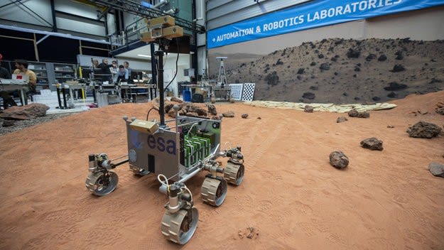
The graph of Torque versus Speed in my recent post (and in Fig.1 below) is the first thing to look at. The first three motor parameters to be determined are the values for Stall Torque, sometimes called Starting Torque, Running Torque and No-Load Speed. Taking a two-wheeled buggy mobile robot as an example project, you need to find out how much torque it takes on each wheel to overcome stiction and get the robot moving. Given enough data on wheel-ground friction, stiction and so forth, it is possible to calculate all you need to know from scratch. But unless you are an engineer working on the next NASA rover, it’s not worth the effort or time. Better to make the buggy first and conduct some experiments on it without the motors and gearboxes fitted.
 Measuring Force
You will need some means of measuring force: a simple spring balance calibrated in grams, for a small robot, or kilograms for a large one. For better accuracy, digital force meters are available – but they’re not cheap. To find those ballpark figures for stall and running torques, tow your robot minus motors along a level surface with the spring balance. Starting from rest, increase the pull until the buggy just begins to roll and note the balance reading. This will provide the value of force needed to overcome stiction. If you continue to pull the robot along at the desired running speed, the lower, running force can be read off. Just to complicate matters, a scale calibrated in grams/kilograms (or even pounds/ounces) measures weight. Fortunately, converting kg to Newtons only involves multiplying by a constant: the acceleration due to gravity, 9.81m/s2.
Calculating Torque
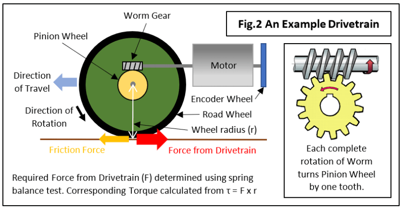
Our experiment has provided an estimate for the linear force needed to move the robot and needs to be matched to a suitable motor. The problem is, we have a linear force requirement, but motors provide rotary force or torque τ. That’s what road wheels are for: converting rotary to linear motion of the robot across the ground. An example of a mobile robot drivetrain is shown in Fig.2 which uses a worm and pinion gearbox to divide down the motor speed to a more usable road wheel speed. Now Wheel Torque in Newton-metres = Linear Force x Wheel Radius or:
τ = F x r Nm
Using this formula with the larger, starting force we have measured, gives us the starting torque that needs to be provided by the drivetrain. The same formula will provide the running torque at the wheel. Note that, in this project, there are two drivetrains – so the torque requirement for each motor is half the calculated value.
Selecting wheels for speed or tractive effort
Micromouse wheels will probably be about 3 cm in diameter: which is quite large for such a small vehicle. There is a simple rule for selecting suitable wheels for your project: Large (diameter) for high-speed, smaller for greater tractive effort. Sports cars and Micromice are built for speed, hence the large wheels. Heavy Goods Vehicles have relatively small wheels for carrying heavy loads at (relatively) slow speed. Planetary rovers move very slowly and need great tractive effort to climb over obstacles on rough terrain. The torque equation above tells the story: reducing the wheel diameter lowers the torque needed from the drivetrain, but at a cost of slower road speed. Alternatively, maintain the motor torque and gain faster acceleration and extra hill-climbing ability.
This is the simple formula for converting linear speed SL in cm/sec to SR rotational speed in rpm:
SR = 60/πD x SL RPM where D is the wheel diameter in cm.
Using our example with SL = 40 cm/s and D = 3 cm, it gives SR = 254 rpm. Just what we need!
Power and Efficiency
A datasheet for a PMDC motor will sometimes contain graphs of Mechanical (Shaft) Power and Efficiency plotted against rotational speed (Fig.1). These plots can be misleading because each requires its own values for the vertical axis and the relationship between each curve can be hard to spot. That’s why my graph has axes calibrated from 0 to 100% of maximum.
The efficiency of a motor describes the ratio of mechanical output power (the bit doing useful work) to the electrical power input. It’s never 100% for a variety of reasons:
- The wire that makes up the motor windings is not a perfect conductor but possesses a small resistance R ohms. Power is wasted in the form of heat according to the formula PI = I2R where I is the armature current.
- The spinning armature is affected by air resistance and the power lost is known as Windage. This loss is obviously zero at zero speed but is proportional to the speed cubed.
- Other losses are due to bearing/brush friction and eddy currents in the iron core.
The curve for Shaft Power can be plotted against Rotation Speed from this equation:
PS = τ x ω Watts where τ = torque in Nm and ω = rotational speed in radians/sec.
You can see from Fig.1 that maximum shaft power occurs at half the stall torque. I’ve already hinted in the example above that the most efficient operating speed is close to the no-load value. But why not at 50% which corresponds to the maximum power output? To establish that, we need a graph of Efficiency against Speed:
Efficiency = PS/(PS+PL) x 100 % where PS = Shaft Power and PL = Power loss due to I2R and Windage.
The resulting plot for Efficiency shows a nice linear rise from zero to about 85% for this particular motor, before it falls off dramatically to near zero at no-load speed. If the Windage is ignored, Efficiency would continue upwards to a final value around 95% at no-load speed - not 100% because a small current is still flowing at the maximum speed. Windage causes that dramatic drop because the air resistance to the rotating armature increases massively as the speed approaches maximum.
Selecting the ‘Sweet Spot’
The best compromise between useful shaft power and wasted energy lies on, or just before, the peak in the efficiency curve. Continuous operation at or near the maximum shaft power point might be problematic because of overheating due to the I2R losses. If this seems likely then thermal calculations will need to be carried out to ensure that the maximum operating temperature is not exceeded.
Adding Feedback Control
All the above calculations are based on the assumption that the motor is run at its rated voltage yielding its maximum stall torque and no-load speed. In an application where the load torque may vary, such as when a mobile robot encounters a slope, the speed will change accordingly. This will probably be considered undesirable, so a feedback control system based on a speed sensor is needed to increase the torque at the set speed by increasing the terminal voltage. Obviously, that’s only possible if the ‘on the flat’ speed is obtained with less than the maximum rated voltage to provide an overhead for hill-climbing. See this article on PID control for further information.
If you're stuck for something to do, follow my posts on Twitter. I link to interesting articles on new electronics and related technologies, retweeting posts I spot about robots, space exploration and other issues.