Smart Restaurant Menu Ordering System using Arduino
Follow article
 Dave from DesignSpark
How do you feel about this article? Help us to provide better content for you.
Dave from DesignSpark
Thank you! Your feedback has been received.
Dave from DesignSpark
There was a problem submitting your feedback, please try again later.
Dave from DesignSpark
What do you think of this article?
Today we find automation systems in every sector whether it be a home, office, or big industry.
In this project, we are creating a restaurant menu ordering system by setting up and programming an Arduino IDE.
So, now let us discuss the building of a Smart Restaurant Project using Arduino
What is a Smart Restaurant Menu Ordering System?
Simply, nowadays restaurants are installing robots to deliver food and tablets for taking orders. By using a digital menu, customers can easily select their items. So, this information will be sent to the kitchen of the restaurant and also displayed on the information board.
Components Required:
- Arduino UNO or Arduino Pro Mini.
- 433MHz RF Transmitter and Receiver
- 2.4” TFT LCD Touch shield
- 16x2 LCD Module & I2C Module
Interfacing TFT LCD Touch shield with Arduino:
- 2.4” TFT LCD Touch shield is a multicolored Arduino UNO/Mega compatible TFT display that has the touch-screen and also with the SD card socket as well. The TFT display module has a bright backlight and also a colorful 240*320 pixels display. This touch shield also consists of individual RGB pixel control that gives this device a much better resolution than the black and white displays.
- The components required for the interfacing TFT LCD Touch shield with Arduino are:
HARDWARE:
- Arduino UNO
- TFT shield
- USB cable
SOFTWARE:
- Arduino IDE
- TFT library for Arduino (spfd5408)
Steps for Installing TFT library in Arduino IDE:
Step 1: We need to download the TFT library for Arduino from the below-given link and need to make it zip if it is not zipped.
Step 2: Next, copy and paste it in the Arduino library folder in the program files as shown in the below fig
Step 3: Open Arduino IDE and then select Sketch->Include Library->Add.ZIP Library and go to the Arduino Library in the program files, where you have copied the zipped downloaded library and then select and open the zipped SPFD5408- Master library
My Computer->C:Drive->Program files->Arduino->libraries.
So, now after opening the SPFD5408 Master Library, we can find that the required library file has been downloaded and installed in the Arduino IDE
Step4: In the Arduino IDE go to the File-> Example-> SPFD5408-master-> spfd5408_grapictest
Open it and complete it and then upload it to the Arduino.
By this, we will get the results on the TFT. Users can modify the code as per their requirements by inserting some samples according to us.
By this, the Interfacing TFT LCD Touch shield with Arduino is done.
This System consists of both RF Transmitter and Receiver sections. The transmitter and receiver side uses Arduino UNO for data processing.
Transmitter Section Circuit:
In this project, the transmitter section consists of an Arduino Uno, RF transmitter, and also TFT display shield. The use of this Transmitter section is used for the ordering from the menu card that is shown on the TFT display. In this section, the Arduino UNO processes all the data and is also the brain of the transmitter side. The RF transmitter module is used in transmitting the selected data to the receiver.
CIRCUIT DIAGRAM: (Transmitter Section)
The pin configuration is shown below:
Data pin of RF module – Digital pin 12 of Arduino
VCC of RF module – 5V of Arduino
GND of RF module – GND pin of Arduino
Schematic Design of the Transmitter Section Circuit
Receiver Section Circuit:
The receiver section of this system consists of the following components: Arduino UNO, RF Receiver, 16*2 LCD module, and also I2C communication module. The main use of the RF receiver is to receive the data from the transmitter section. The LCD module is used in displaying the received data. A buzzer is also used to make a sound whenever a new order is placed in the restaurant.
The pin configuration of the circuit is shown below:
Data pin of RF receiver – Digital pin 11 of the Arduino
VCC of the RF receiver – 5V of the Arduino
GND of RF receiver – GND of the Arduino
Positive pin of the Buzzer – Digital pin 2 of the Arduino
Negative pin of the Buzzer – GND pin of the Arduino
SCL pin of the I2C module – A5 pin of the Arduino
SDA pin of the I2C module – A4 pin of the Arduino
VCC of the I2C module – 5V of the Arduino
GND of the I2C module – GND of the Arduino
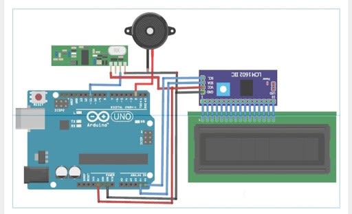
Schematic Circuit Design of Receiver Section Module
CODE:
Code for Transmitter (TFT LCD)
#include <RH_ASK.h>
#include <SPI.h> // Not actually used but needed to compile
#include <SPFD5408_Adafruit_GFX.h> // Core graphics library
#include <SPFD5408_Adafruit_TFTLCD.h> // Hardware-specific library
#include <SPFD5408_TouchScreen.h>
const char *msg ;
RH_ASK driver;
#define YP A1 // must be an analog pin, use "An" notation!
#define XM A2 // must be an analog pin, use "An" notation!
#define YM 7 // can be a digital pin
#define XP 6 // can be a digital pin
#define TS_MINX 125
#define TS_MINY 85
#define TS_MAXX 965
#define TS_MAXY 905
TouchScreents = TouchScreen(XP, YP, XM, YM, 300);
#define LCD_CS A3
#define LCD_CD A2
#define LCD_WR A1
#define LCD_RD A0
// optional
#define LCD_RESET A4
#define REDBAR_MINX 80
#define GREENBAR_MINX 130
#define BLUEBAR_MINX 180
#define BAR_MINY 30
#define BAR_HEIGHT 250
#define BAR_WIDTH 30
Adafruit_TFTLCDtft(LCD_CS, LCD_CD, LCD_WR, LCD_RD, LCD_RESET);
#define BLACK 0x0000
int BLUE = tft.color565(50, 50, 255);
#define DARKBLUE 0x0010
#define VIOLET 0x8888
#define RED 0xF800
#define GREEN 0x07E0
#define CYAN 0x07FF
#define MAGENTA 0xF81F
#define YELLOW 0xFFE0
#define WHITE 0xFFFF
#define GREY tft.color565(64, 64, 64);
#define GOLD 0xFEA0
#define BROWN 0xA145
#define SILVER 0xC618
#define LIME 0x07E0
void drawHome()
{
tft.fillScreen(WHITE);
tft.drawRoundRect(0, 0, 319, 240, 8, WHITE); //Page border
tft.fillRoundRect(30, 40, 100, 40, 8, GOLD);
tft.drawRoundRect(30, 40, 100, 40, 8, WHITE); //Dish1
tft.fillRoundRect(30, 90, 100, 40, 8, GOLD);
tft.drawRoundRect(30, 90, 100, 40, 8, WHITE); //Dish2
tft.fillRoundRect(30, 140, 100, 40, 8, GOLD); //Dish3
tft.drawRoundRect(30, 140, 100, 40, 8, WHITE);
tft.fillRoundRect(10, 190, 190, 40, 8, CYAN);
tft.drawRoundRect(10, 190, 190, 40, 8, WHITE); //Call Waiter
tft.fillRoundRect(180, 40, 100, 40, 8, GOLD);
tft.drawRoundRect(180, 40, 100, 40, 8, WHITE); //Dish4
tft.fillRoundRect(180, 90, 100, 40, 8, GOLD);
tft.drawRoundRect(180, 90, 100, 40, 8, WHITE); //Dish5
tft.fillRoundRect(180, 140, 100, 40, 8, GOLD);
tft.drawRoundRect(180, 140, 100, 40, 8, WHITE); //Dish6
tft.fillRoundRect(210, 190, 100, 40, 8, GREEN);
tft.drawRoundRect(210, 190, 100, 40, 8, WHITE); //Bill
tft.setCursor(60, 0);
tft.setTextSize(3);
tft.setTextColor(LIME);
tft.print(" Menu");
tft.setTextSize(2);
tft.setTextColor(WHITE);
tft.setCursor(37, 47);
tft.print(" Dish1");
tft.setCursor(37, 97);
tft.print(" Dish2");
tft.setCursor(37, 147);
tft.print(" Dish3");
tft.setCursor(23, 197);
tft.print(" Call Waiter");
tft.setCursor(187, 47);
tft.print(" Dish4");
tft.setCursor(187, 97);
tft.print(" Dish5");
tft.setCursor(187, 147);
tft.print(" Dish6");
tft.setCursor(227, 197);
tft.print(" Bill");
// delay(500);
}
intoldcolor, currentcolor, currentpcolour;
void setup(void) {
tft.reset();
tft.begin(tft.readID());
Serial.begin(9600);
Serial.println();
Serial.print("reading id...");
delay(500);
Serial.println(tft.readID(), HEX);
tft.fillScreen(BLACK);
tft.setRotation(1);
tft.setTextSize(3);
tft.setTextColor(WHITE);
tft.setCursor(50, 140);
tft.print("Loading...");
tft.setTextColor(tft.color565(255, 255, 0));
tft.setCursor(30, 70);
tft.print("By:");
tft.setCursor(10, 100);
tft.print("CircuitDigest.Com");
for (inti; i< 250; i++)
{
tft.fillRect(BAR_MINY - 10, BLUEBAR_MINX, i, 10, RED);
delay(0.000000000000000000000000000000000000000000000000001);
}
tft.fillScreen(BLACK);
if (!driver.init())
Serial.println("init failed");
drawHome();
pinMode(13, OUTPUT);
}
#define MINPRESSURE 10
#define MAXPRESSURE 1000
void transmit()
{
driver.send((uint8_t *)msg, strlen(msg));
driver.waitPacketSent();
delay(1000);
}
void loop()
{
digitalWrite(13, HIGH);
TSPoint p = ts.getPoint();
digitalWrite(13, LOW);
// if sharing pins, you'll need to fix the directions of the touchscreen pins
//pinMode(XP, OUTPUT);
pinMode(XM, OUTPUT);
pinMode(YP, OUTPUT);
//pinMode(YM, OUTPUT);
if (p.z>ts.pressureThreshhold)
{
p.x = map(p.x, TS_MAXX, TS_MINX, 0, 320);
p.y = map(p.y, TS_MAXY, TS_MINY, 0, 240);
if (p.x> 180 &&p.x< 280 &&p.y> 190 &&p.y< 230 &&p.z> MINPRESSURE &&p.z< MAXPRESSURE)
{
Serial.println("Dish1");
msg = "Dish1 Ordered";
transmit();
tft.fillRoundRect(30, 40, 100, 40, 8, WHITE);
delay(70);
tft.fillRoundRect(30, 40, 100, 40, 8, GOLD);
tft.drawRoundRect(30, 40, 100, 40, 8, WHITE);
tft.setCursor(37, 47);
tft.println(" Dish1");
delay(70);
}
if (p.x> 180 &&p.x< 280 &&p.y> 140 &&p.y< 180)
{
Serial.println("Dish2");
msg = "Dish2 Ordered";
transmit();
tft.fillRoundRect(30, 90, 100, 40, 8, WHITE);
delay(70);
tft.fillRoundRect(30, 90, 100, 40, 8, GOLD);
tft.drawRoundRect(30, 90, 100, 40, 8, WHITE);
tft.setCursor(37, 97);
tft.println(" Dish2");
delay(70);
}
if (p.x> 180 &&p.x< 280 &&p.y> 90 &&p.y< 130)
{
Serial.println("Dish3");
msg = "Dish3 Ordered";
transmit();
tft.fillRoundRect(30, 140, 100, 40, 8, WHITE); //rgb led
delay(70);
tft.fillRoundRect(30, 140, 100, 40, 8, GOLD); //rgb led
tft.drawRoundRect(30, 140, 100, 40, 8, WHITE); //rgb led
tft.setCursor(37, 147);
tft.print(" Dish3");
delay(70);
}
if (p.x> 210 &&p.x< 310 &&p.y> 40 &&p.y< 80)
{
Serial.println("Call Waiter");
msg = "CallingWaiter";
transmit();
tft.fillRoundRect(10, 190, 190, 40, 8, WHITE);
delay(70);
tft.fillRoundRect(10, 190, 190, 40, 8, CYAN);
tft.drawRoundRect(10, 190, 190, 40, 8, WHITE);
tft.setCursor(23, 197);
tft.print(" Call Waiter");
delay(70);
}
if (p.x> 30 &&p.x< 130 &&p.y> 190 &&p.y< 230)
{
Serial.println("Dish4");
msg = "Dish4 Ordered";
transmit();
tft.fillRoundRect(30, 40, 100, 40, 8, WHITE);
delay(70);
tft.fillRoundRect(30, 40, 100, 40, 8, GOLD);
tft.drawRoundRect(30, 40, 100, 40, 8, WHITE);
tft.setCursor(187, 47);
tft.print(" Dish4");
delay(70);
}
if (p.x> 30 &&p.x< 130 &&p.y> 140 &&p.y< 180 )
{
Serial.println("Dish5");
msg = "Dish5 Ordered";
transmit();
tft.fillRoundRect(180, 90, 100, 40, 8, WHITE);
delay(70);
tft.fillRoundRect(180, 90, 100, 40, 8, GOLD);
tft.drawRoundRect(180, 90, 100, 40, 8, WHITE);
tft.setCursor(187, 97);
tft.print(" Dish5");
delay(70);
}
if (p.x> 30 &&p.x< 130 &&p.y> 90 &&p.y< 130)
{
Serial.println("Dish6");
msg = "Dish6 Ordered";
transmit();
tft.fillRoundRect(180, 140, 100, 40, 8, WHITE);
delay(70);
tft.fillRoundRect(180, 140, 100, 40, 8, GOLD);
tft.drawRoundRect(180, 140, 100, 40, 8, WHITE);
tft.setCursor(187, 147);
tft.print(" Dish6");
delay(70);
}
if (p.x> 10 &&p.x< 210 &&p.y> 40 &&p.y< 80)
{
Serial.println("Bill");
msg = "Customer Bill";
transmit();
tft.fillRoundRect(210, 190, 100, 40, 8, WHITE);
delay(70);
tft.fillRoundRect(210, 190, 100, 40, 8, GREEN);
tft.drawRoundRect(210, 190, 100, 40, 8, WHITE);
tft.setCursor(227, 197);
tft.print(" Bill");
delay(70);
}
}
}
Code for Receiver
#include <RH_ASK.h>
#include <SPI.h> // Not actualy used but needed to compile
#include <LiquidCrystal_I2C.h>
//String msg;
LiquidCrystal_I2C lcd(0x27, 16, 2);
RH_ASK driver;
#define buzzer 2
void setup()
{
Serial.begin(9600); // Debugging only
pinMode(buzzer, OUTPUT);
lcd.begin();
lcd.clear();
if (!driver.init())
Serial.println("init failed");
}
void loop()
{
uint8_t buf[17];
uint8_t buflen = sizeof(buf);
if (driver.recv(buf, &buflen)) // Non-blocking
{
inti;
digitalWrite(buzzer, HIGH);
delay(1000);
digitalWrite(buzzer, LOW);
// Message with a good checksum received, dump it.
Serial.print("Message: ");
Serial.println((char*)buf);
lcd.clear();
lcd.setCursor(0,0);
lcd.print("T1:");
lcd.print((char*)buf);
}
}
Explanation of the CODE:
- Firstly, the libraries used in the project should be downloaded.
- The libraries can be downloaded from the below-given links:
https://github.com/PaulStoffregen/RadioHead
https://github.com/JoaoLopesF/SPFD5408
- Here, the first one RadioHead library is used for the RF transmitter/receiver module and the second one SPFD5408 library is used for the TFT display
Transmitter Section Code:
- By including all the libraries, start the code.
- RH_ASK.h library is the library used in the communication between the transmitter and the receiver modules.
- SPFD5408_Adafruit_GFX.h is the Core graphics library for the TFT display.
- Next, create an object called 'driver' for the library RH_ASK
- Now, define the minimum and maximum calibrated X and Y-axis values for the TFT display
- Next, draw a layout inside the draw home function for the TFT screen. The tft.fillscreen is used in setting the background color
- Tft.drawRoundRect function is used in creating a filled rectangle. Syntax of the tft.drawRoundRect function is shown below:
- Tft.drawRoundRect (int16_t x0, int16_t_y0, int16_t w, int16_t h, int16_t radius, unit16_t color )
Where;
x0= X co-ordinate of the starting point of the rectangular
y0= Y coordinate of the starting point of the rectangular
w= Width of the rectangular
h= Height of the rectangular
radius= radius of round corner
color= Color of the rectangle
- Tft.fillRoundRect function is used to draws a filled rectangle and the syntax is shown in the code
- After creating the required buttons on the TFT screen, then display the text on the buttons.
- TFT.setCursor is used in setting the cursor from where we want to start the text
- Next, Inside the void transmit function, send the data to the receiver side for every 1 second
- Now, inside the void loop function, read the raw ADC value using the ts.getPoint function
- By using the map function convert the Raw ADC values to Pixel Co-ordinates
- Next, after converting the Raw ADC values into the pixels co-ordinate, enter the pixel coordinates for the 1st button that is for Dish 1 button
- It means that if someone touches the screen between this area then the message will be automatically sent to the receiver side
- Use the same procedure for all the other buttons as per your requirement
Receiver Section Code:
- Now, for the RF receiver section, we have to include the libraries for the RF receiver and LCD module
- Next include the SPI.h library for the establishment an SPI communication between the RF receiver and Arduino
- Inside the void loop function, check for the transmitted messages continuously
- If the receiver module receives a message, then the message has to be displayed on the LCD module and makes a beep sound.
- By this, the explanation of the code is successfully done.
Working of the Project:
This project Smart Restaurant Project using Arduino consists of the TFT Display and the RF transmitter/receiver module.
The working of the transmitter section will consist of Arduino UNO, TFT display and also an RF transmitter.
By using this transmitter section the customer can select the food items and can place the order.
Whereas the receiver section consists of an Arduino UNO, LCD module, RF receiver and a Buzzer that is installed in the restaurant kitchen to track the ordered items.
So, by using this order can be placed directly from the customers' table to the restaurant kitchen.
PRACTICAL IMPLEMENTATION:
Practical Implementation of Transmitter Section Circuit

Practical Implementation of Receiver Section Circuit
The output of the Project:
- Firstly, after connecting the hardware and uploading the code for both the transmitter and receiver section, it’s time to check and test the project.
- For testing the project, firstly press a button on the TFT display.
- It will display the dish name with the table number that is T1, T2, etc on the LCD module which is connected to the receiver side with a buzzer sound intimating that the order has been received.
- By this, the project is successfully done.