RS Industrial Demonstrators Design & Build
Follow article
 Dave from DesignSpark
How do you feel about this article? Help us to provide better content for you.
Dave from DesignSpark
Thank you! Your feedback has been received.
Dave from DesignSpark
There was a problem submitting your feedback, please try again later.
Dave from DesignSpark
What do you think of this article?
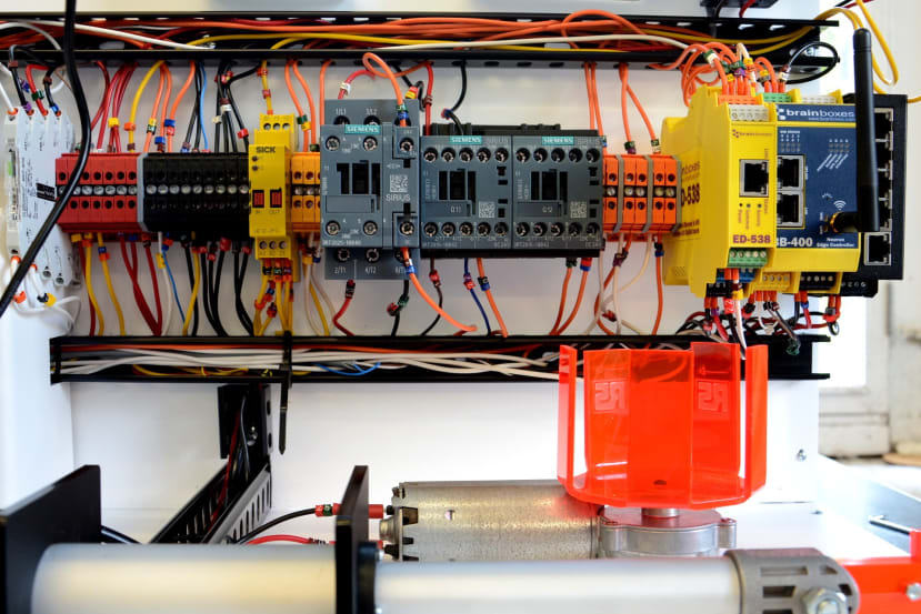
Brainboxes BB-400 NeuronEdge Controller plus ED-538 I/O module, together with PanelPilotACE, form the heart of demonstrator units that showcase industrial products.
In this post, we take a look at the design and build of two industrial demonstrator units which will be used at trade shows and combine a Brainboxes BB-400 controller plus ED-538 I/O, together with a PanelPilotACE display, along with buttons, relays, contactors, indicators, sensors, and actuators.
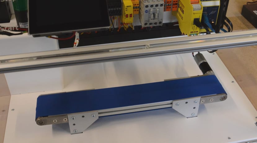
The first demonstrator unit has a miniature conveyor belt with start/stop buttons, optical guarding and emergency stop, plus voltage, current, and power indication.

The second has the same features, but instead of the conveyor belt is based around a simple process with rotary (881-4523) and linear (177-4514) actuators.
Raspberry Pi-powered
Traditional programmable logic controllers (PLCs) provide plentiful robust I/O and are designed to stand the rigours of industrial environments. However, they typically have fairly limited programming options — e.g. Structured Text — and use a “deeply embedded” processor that is capable of executing only relatively simple logic.
The Raspberry Pi, on the other hand, benefits from a reasonably powerful processor and can run many tasks in parallel. It can be programmed with a vast array of programming languages, libraries, and frameworks, with support for many different communications protocols. However, while they are put to an astounding number of different uses, the classic boards are not qualified for industrial environments and require additional circuitry for buffering and protecting I/O, for example.
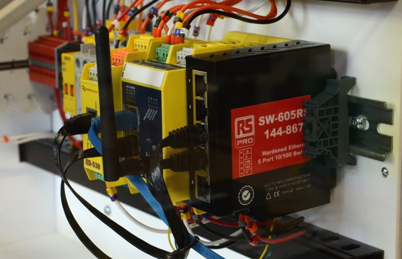
The Brainboxes BB-400 (181-7467) combines the best of both worlds in a solution that is based on the Raspberry Pi Compute Module which is targeted at industrial applications. Packaging this in a DIN rail enclosure along with a power supply that can take a 5-30V supply, a supercapacitor powered integrated uninterruptible power supply (UPS) for data integrity, 8x digital I/O, dual-Ethernet and WiFi. Not to mention an easy-to-use web interface and industrial protocol support.
As such the BB-400 is the perfect solution for Industrial IoT (IIoT) applications, where it can act as an “edge controller” which is able to read sensors and other inputs, while controlling actuators, implementing local logic and communicating with remote central systems where required. Here our use will be very simple indeed, but the sky would be the limit when it comes to expanding our system and enabling integration with other, e.g. ERP and cloud, systems.
Additional I/O

We needed some additional I/O and this gave us an opportunity to show how the BB-400 capabilities can be expanded via the Brainboxes I/O module range. Since we had to control contactors and required some additional inputs, the ED-538 (789-8144) with its 4x relay outputs and 8x digital inputs, would give us everything that we needed and with some capacity to spare. This has an Ethernet interface and is driven using a simple ASCII command protocol that would be easy enough to interact with using our programming language of choice on the BB-400.
An HMI and more
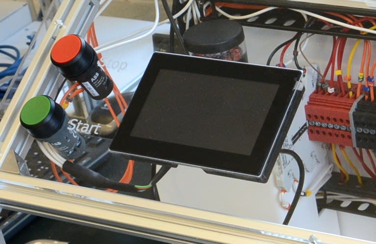
The PanelPilot SGD 43-A (800-6712) is a 4.3” capacitive touch display that can be used as a human-machine interface (HMI) and much more. This also features digital I/Os, plus analogue inputs, with the ability to implement PID and PWM control, along with data logging and graphing, etc.

Here it is simply being used with 2x analogue inputs — one measuring voltage and a second measuring current via a shunt (810-3261) and signal conditioner (135-7396) . Custom screens were then created in its design tool, that display voltage and current measured, plus a power calculation.
Safety first
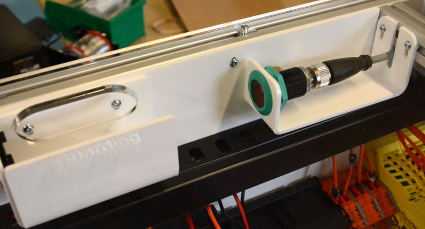
An industrial automation solution would not be complete without appropriate safety measures and we decided upon the combination of optical guarding (228-992) and emergency stop button (183-4520) . The signals output from each are then fed into a dual-channel safety relay (701-9216) , the contacts of which are wired in serial and used to provide our enable current.

Hence only when both safety relay inputs are positive do we have current which is used to supply contactor coils via the BB-400 controlled relay contacts of the ED-538 module.
Process inputs

There are many different ways we could have provided process control inputs and we settled for a pair of industrial push buttons for start and stop. These are wired between ground and BB-400 digital inputs. An alternative solution might have been to configure the PanelPilotACE to have on-screen buttons that drive its digital I/Os and then interface these with the BB-400.
We also wanted to ascertain whether enable current is present or not, since this reflects the safety state and there is no point running our process if contactors, and therefore actuators, will not energise. This is achieved by connecting the enable current circuit to a digital input on the ED-538.
Process state
The process state is reflected via LED tower beacons which also provide a safety function in very visibly indicating whether the process is running or not. The conveyor unit has a dual colour beacon (849-5374) and the rotary plus linear actuator unit has a three colour tower (865-5093) . These are driven by digital outputs on the BB-400.
A note on reversing
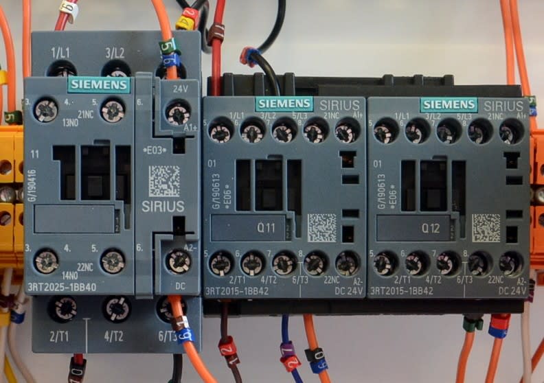
The conveyor belt unit is quite simple in that we just need an ordinary contactor — in fact, we could have simply used a relay, but these are industrial demonstrators after all! — to switch the supply to it. However, the linear actuator operates in both forward and reverse directions, which means reversing the current through its motor. This is achieved using a reversing contactor (861-3584) , which can be seen above on the right-hand side and is comprised of two contactors with special interlocking features, which means that only one can ever be energised at any one time.
The reversing contactor is wired such that with 3-phase mains input when one side (an individual contactor) is energised the 3-phase is switched straight through, but when the other side is energised two phases are swapped and a powered motor would then operate in the reverse direction.
The ordinary contactor to the left (706-1333) is used to switch power to the rotary actuator and while we could operate in the reverse direction also, we decided to keep things simple and have it run forward only. Obviously we’re not using 3-phase mains power here, but both types of contactor work just fine with low voltage DC and we simply end up with unused contacts.
Python code
import brainboxes
from binascii import unhexlify
import time

# Initialise variables

enst = False
runst = False
prevRunst = False
step = 0

# Pause between beacon transitions

beaconDelay = 2

# Duration of each process step

stepTime = 5

# API endpoints

ed538ip = '192.168.127.254'
bb400ip = '127.0.0.1'
Fragment of the code used to implement process control
Since the BB-400 is powered by a Raspberry Pi Compute Module running Linux, there is no shortage of options when it comes to programming languages that could be used. The only real requirement being that it must have TCP/IP networking support since this is needed to communicate with an application programming interface (API) on the BB-400 in order to interact with its I/O, and also on the ED-538 for the remote/expanded I/O. The BB-400 options include a REST interface and simple ASCII protocol, while the ED-538 supports ASCII protocol only.
For consistency, we decided to use the ASCII protocol to interface with both the BB-400 and ED-538 I/O. Python was selected as the programming language since this lends itself to rapid prototyping, is easy to read and powerful. Also, Brainboxes provide an example Python class/library for use with ASCII protocol, which made it possible to get up and running faster.
The code for both demonstrators can be found on GitHub. To summarise, we first created some useful functions:
- getEnable() reads a pin on the ED-538 that detects the presence of enable current.
- getRun() reads pins on the BB-400 that are connected to the start/stop buttons.
- setBeacon() writes to pins on the BB-400 that control the tower beacon LEDs.
- setActuator() sets the state of the ED-538 relay outputs that are wired to contactors.
- runProcess() evaluates the current process step and sets the beacon and actuators accordingly.
We then run in a loop and have a simple state machine where we check for enable current (or lack of, suggesting emergency stop!) and start/stop button presses.
With the conveyor, we’re either running or stopped, so the state machine is about as simple as it could be. However, with the rotary and linear actuator unit we step through running the motor, then the linear actuator forwards, followed by the linear actuator in reverse, and repeat. This also has as three colour tower beacon and so from the stopped state we first go into an amber state, followed by green and at this point, the aforementioned process is run in a loop until the stop or emergency stop button is pressed, or optical guarding is triggered. Timing is done by checking the system clock.
It should be noted that there is almost certainly scope for improvement, the code has not been optimised and it is definitely not intended for any sort of production use. Indeed, in a real-world application with hazardous machinery, you wouldn’t have beacon indicators under software control and instead, these would be directly integrated with the safety or drive circuits. The code is being shared here just to provide an example of how you can interface with Brainboxes I/O.
Further reading
To find out more about some of the key components used, see the blog posts: