Return of Arcade
Follow article Dave from DesignSpark
How do you feel about this article? Help us to provide better content for you.
Dave from DesignSpark
Thank you! Your feedback has been received.
Dave from DesignSpark
There was a problem submitting your feedback, please try again later.
Dave from DesignSpark
What do you think of this article?
This project has been developed as part of a final degree project of the MsC in Industrial Engineering (speciality in electronics) at the Electrical, Electronics and Communications Department of the Public University of Navarra. The aim of this project is to build the classic video game “Tetris” using the microcontroller PIC16F876A. The development of the project will be divided into three different parts: the electronic circuit design (using DesignSpark PCB), the programming of the microcontroller and the 3D modelling (using DesignSpark Mechanical).
It will be necessary to use two 8x8 LED matrices that will work as a screen, two Johnson counters that will turn on the screen, a joystick to control the movement of the piece, a microcontroller to govern the whole process and a bunch of electronic components to join them all.
1.Electronic circuit design
Microcontroller
The control circuit is based on the PIC16F876A microcontroller, which works at 5V. Furthermore, an external oscillator working at 20 MHz (0.2µs per instruction cycle) will be used. In-circuit Serial Programming (ICSP) connector will be used In order to connect the PC with the microcontroller and enable direct programming/debugging of the robot.
Linear voltage regulator
To power up the Tetris an 8.4V rechargeable battery will be employed. Since the operating voltage of the microcontroller is of 5V, a linear voltage regulator (7805) will be necessary to decrease the voltage from 8.4V to 5V.
LED matrix
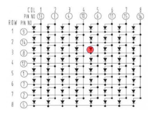
The matrix that will be used is the 1088AS; this matrix has the anodes in the columns of the matrix, while the cathodes are in the lines. There are eight 330 Ω resistors connected to the anodes of the LEDs, in that way that the current through the LEDs will be limited to ∼15mA. So, if we would like to turn on the LED that is marked in the figure, we would need to put the third line at 0V and the fifth column at 5.
Johnson counters
In order to save some pins of the microcontroller, two Johnson decade counters have been used. Each output of the counter is connected to a line of the screen (LED matrices), so when a pulse is sent to the input of the counter, this counter will advance and turn on the next line.
Joystick
It will also be necessary to use a joystick that allows the user to control the piece that is falling down in the screen. This joystick has to analog outputs that vary their values in function of the position of the joystick as it is represented in the figure, so these outputs will be connected to the analog inputs of the microcontroller.

Components
The components needed for the development of the project are detailed below:
- PIC16F876A.
- 20MHz crystal oscillator.
- 5V linear voltage regulator.
- 2 Johnson counters.
- Piezoelectric buzzer.
- 2 8x8 LED matrices.
- Joystick.
- Red LED.
- Several discrete components, such as connectors, NPN transistors, resistors and capacitors (detailed in the BOM list attached at the end of the article).
2.PCB design
The design of the PCB has been done with the software DesignSpark PCB 8.0. The components have been placed in order to save as much space as possible and the package of the components has been selected accordingly (SMD) so it will help to save more space. To reduce the number of tracks and vias to the maximum the bottom layer is used as GND plane. The following figures show the 3D representation of the PCB prototype:

3.Programming environment
This section describes the functions of the Tetris game and the number of pins of the microcontroller that are used:
|
FUNCTION |
PINS |
|
Joystick |
2 analogical and 1 digital |
|
Johnson counter (x2) |
4 pins |
|
Buzzer |
1 pin (PWM) |
|
LED matrices |
8 pins |
|
Total |
16 |
Adding the 5V and GND pins, the external oscillator pins and the modular connection pins, it makes a total of 24 pins out of the 28 pins available in the microcontroller used for this project (PIC16F876A).

The microcontroller has been programmed using the Integrated Development Environment (IDE) MPLAB 8.92 and the ICD2 debugger as a depuration tool. The programming language used for this project is C by means of the HI-tech compilation tool. All the code has been attached at the end of the article but some of the main microcontroller integrated hardware used in the project is described below.
Timers
Three timers have been used for the implementation of the project: TMR0, TMR1 and TMR2. The different functions and operation of each timer is described in the following lines:
- PWM module (associated to TMR2).
- Duration of the melody notes (duration of a semiquaver=100ms).
- Activation of the A/D converter (100ms).
- Falling piece (1 second).
- Line change on the Johnson counters.
|
TMR0 |
TMR1 |
TMR2 |
|
3.28ms |
100ms |
Depends on the note |
|
Line change on the Johnson counters.
|
|
PWM |
PWM module
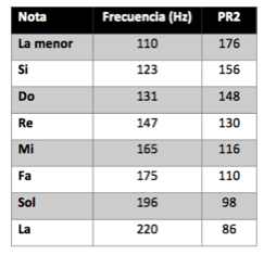
The PWM module of the CCP2 will be used to generate the notes of the melody. The value of PR2 depends on the note that is being played at each moment:
P1 and P2 are the post- and pre-divisors of the Timer 2 and Ti is the duration of a machine cycle of the microcontroller (0.2µs).
A/D converter
The A/D converter will be used for the implementation of the Joystick, which has two analog outputs. These outputs will be connected with the pins RA0 and RA1 of the microcontroller. This module isn’t able to carry out the conversion of two pins at the same time, so every 100ms the microcontroller will change the input pin of an internal analog multiplexer connected to de A/D converter input.
Interruptions
The interruptions of the timers and the A/D converter will be needed for the correct operation of the Tetris game in order to maintain proper timings and delays.
4.3D Modeling
The design of the case of the Tetris is divided into two parts, the base and the top; the top must have two holes: one for the joystick and the other one for the screen. The design has been made with the software DesignSpark Mechanical and then printed with a 3D printer.
