How true differential scope inputs boost probing safety and precision
Follow article
 Dave from DesignSpark
How do you feel about this article? Help us to provide better content for you.
Dave from DesignSpark
Thank you! Your feedback has been received.
Dave from DesignSpark
There was a problem submitting your feedback, please try again later.
Dave from DesignSpark
What do you think of this article?
From line-voltage and embedded power supplies to audio and serial data communication, differential voltage measurements deliver tangible benefits to scope users trying to track down pesky signals invisible to conventional, ground-referred probes.
As all first-year EE graduates know, the voltage measured between two points is equal to the electrical potential difference between them. Place the probes of a DVM across a battery’s terminals and, bingo, that difference translates into a reading in volts on the meter. In most cases, DVMs have floating inputs with no absolute voltage reference. This is tacit knowledge that we all understand. Voltage is easily measured. After all, you don’t even have to break the circuit to get a reading.
But beware - danger lurks
Voltage measurement becomes a little trickier when using an oscilloscope. That is because scopes are almost always designed with single-ended (SE), ground-referred inputs (Figure 1). Each measurement channel shares this common ground reference - it’s the outer sleeve of the BNC. So, scopes usually measure amplitudes relative to ground.
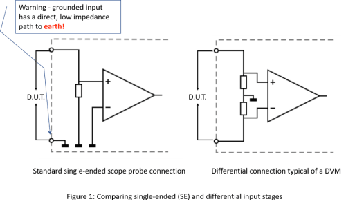

The problem of single-ended, ground referred probes visualized.
That may not sound like a significant functional difference but it has major consequences. Most notably, without caution, probing power circuits risks inadvertently creating a short. Consider that a grounded SE probe is normally[1] tied, internally, directly to the equipment chassis and then, via mains cabling, to earth. That is a low-impedance pathway with an important safety benefit. It’s better than having large currents forced to find a way to ground via organic matter that unluckily gets in the way. Like the odd test engineer.
([1] In the case of PC-based scopes, there is not always a ground return path. Operated via USB, from a laptop disconnected from the line (mains), they can act as a true floating system.)
Probe a higher voltage node of a power circuit with a standard SE probe and often the result will be sparks or the rapid shutdown of the system from an overcurrent event. You may not even have started probing. Even beforehand, an inappropriately placed grounded crocodile clip can cause a short!
Float to safety
So what is the solution? How can voltage measurements be made safely with a scope under these conditions?
The answer lies in removing the path to ground. Figure 1 shows a simplified differential input stage (the right-hand side). The input ‘floats’, ensuring that any potential difference between the probe pins is measurable. There is no likelihood of shorts as there is no low-impedance ground path.
Perhaps the simplest approach to emulate differential measurements on a standard scope is to exploit the scope’s mathematical functions. These can be applied across a channel pair. Connect SE probes to two channels (say channels 1 and 2) and then short their ground clips together while ensuring that they stray nowhere near the device under test (DUT). You still need to avoid potential shorts! Finally, by subtracting channel 2 from channel 1 you will observe a pseudo-differential result on screen.
Note that this comes at the expense of a lost channel! Also undesirable, any voltage errors in this system are additive. Using two channels for a single, pseudo-differential measurement means that two errors creep in - doubling their impact.

Figure 2 – Rejection of common mode noise
One PC-based oscilloscope eases differential measurements
Active differential probes offer superior performance over their passive, SE cousins. High common mode rejection combines with low input capacitance. This reduces circuit loading and noise to uncover more of what’s really going on. Helping you see the difference. So now, having learnt the benefits of differential inputs, you’re probably wondering why they are not more widely found on oscilloscopes. Why are they an add-on feature?
Simply stated, extra complexity increases manufacturing costs and raises the price. But imagine if differential measurement capabilities were pre-packaged in a highly portable form factor. The PicoScope 4444 does exactly that. It offers a high-resolution, PC-based scope with four integrated, differential inputs.
See the difference
Notice the product’s unique fascia – no BNCs. The PicoScope 4444 displaces traditional connectors with four, robust 9-pin D-type connectors, highlighting distinctive differences under its skin. The novel connectors enable a family of smart, differential probes to be attached. Additional pins facilitate digital control between the probe electronics and the scope. They also supply power and enable automatic probe identification.
I
See even more
Beyond obvious safety benefits, you can extract important information even in low-voltage circuits where conventional SE probes are ineffective. Typical applications are any featuring important floating nodes, which are inherently sensitive to being collapsed by the ground return loop as soon as the croc clip bites! Incidentally, there are many systems where significant common mode noise renders SE measurements useless.

Consider the simple embedded DC/DC power circuit shown. From a quick glance (Figure 3a) it’s not immediately apparent if the power inductor is grounded or floating. It’s a complicated picture as the inductor current is determined by several factors; namely absolute levels of VIN, VOUT and the static DC load current. It makes for an interesting differential measurement test case
The ISL9120, a multi-mode converter IC, is capable of buck, boost or pass-through operation. Four internal IC switches surround the inductor (Figure 3b) determining current flow. Considering all the switch combinations, it’s difficult to unpick what instantaneous voltages appear across the inductor (at LX1 & LX2). Add to this the various switching modes, complicating triggering, and this circuit cries out for differential probes. Next time around we’ll use the PicoScope 4444 to dig deeper into what’s happening to voltage across the inductor.
Offering flexibility, precision and the safety of differential inputs, the PicoScope 4444 enhances any engineer’s workbench. Moreover, simple BNC to D-type adapters are available to allow traditional probes to be used when that’s all that is needed. But the 4444’s elegance derives from eliminating troublesome ground loops. A small innovative step that helps avoid shocking short circuits, calming the nerves of engineers everywhere.