EMI Debugging with an Oscilloscope
Follow article Dave from DesignSpark
How do you feel about this article? Help us to provide better content for you.
Dave from DesignSpark
Thank you! Your feedback has been received.
Dave from DesignSpark
There was a problem submitting your feedback, please try again later.
Dave from DesignSpark
What do you think of this article?
Benefits of using an oscilloscope
Oscilloscopes are the workhorses for power electronics engineers. With powerful and easy-to-use FFT analysis capabilities, their application fields extend to EMI debugging – and that saves a lot of time and money. A typical task is verifying the effectiveness of an EMI filter – early in the development phase.
Rohde & Schwarz oscilloscopes offer a powerful, easy-to-use FFT analysis functionality to measure the magnitude of the frequency component. Users are able to see the time domain related signals at the same time and can therefore correlate unwanted spectral emissions with time domain events. This makes these oscilloscopes powerful standalone instruments for performing early conducted emission tests on power electronics designs. They can easily detect electromagnetic interference from electronic circuits with high speed and accuracy. The basic working principle of an oscilloscope is to capture signals when the input signal exceeds a specific trigger value, which helps to capture the peaks of the noise signal.
Overall, the major benefits of using an oscilloscope can be summarized as follows:
- Visible correlation between frequency and time domain
- Wide and instantaneous frequency coverage
- Deep memory for capturing long signal sequences
- Gated FFT analysis for correlated time-frequency analysis
- Frequency masks for triggering on intermittent events with lab-class instruments
- Overlapping FFT computation with color grading with lab-class instruments
Evectiveness of the EMI filter
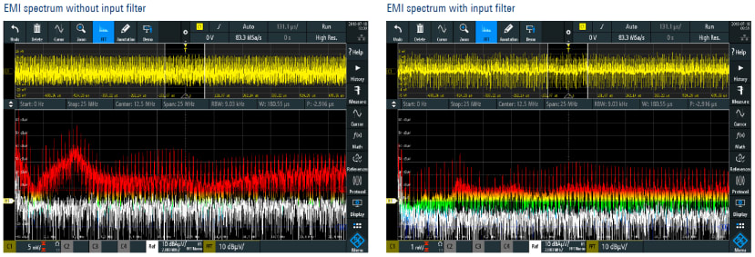
The FFT functionality of Rohde & Schwarz oscilloscopes is a powerful feature that enables designers to debug conducted emissions of power supplies. When using an oscilloscope to test conducted emissions, the R&S®RTM3000 plus a line impedance stabilization network (LISN) are an ideal combination for debugging. To measure conducted emissions of a power supply, you need an LISN, for example the R&S®HM6050-2, to decouple the device under test (DUT) from the external power supply.
Once the FFT is applied to the signal, and by selecting the center frequency and span, an oscilloscope can show the time domain and the frequency domain traces – comparable to what you can find on a spectrum analyzer. When comparing emission limits, you need to take into account that the signal might be attenuated due to the LISN. The EMI filter of the switched mode power supply is responsible for the reduced EMI spectrum; the noise generated at the input of the DC/DC converter is clearly visible in the left screenshot. With the low-pass-filter, you see that the conducted emissions on the input are effectively attenuated. For some frequencies, up to 30 dB attenuation is visible.
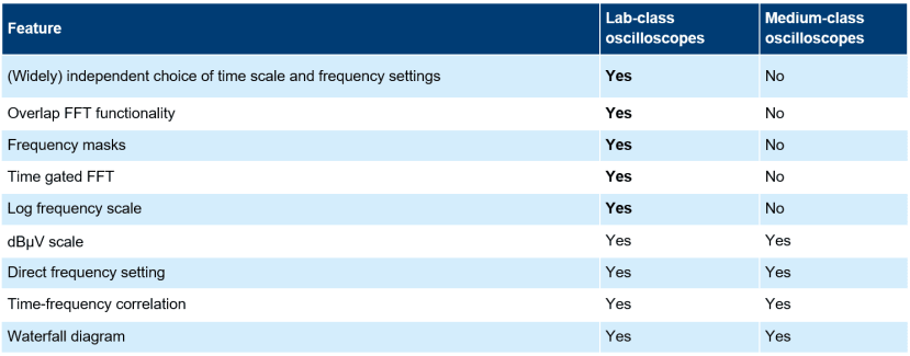
Comparison: lab-class vs. medium-class oscilloscopes
For debugging and locating emission sources using an oscilloscope, a combination of the R&S®RTM3000 or the R&S®RTA4000 oscilloscope and the R&S®HZ-17 near-field probe set can do an excellent job. In addition to that, lab-class oscilloscopes have extended trigger and analysis capabilities that provide valuable tools for analyzing difficult EMI problems. Lab-class oscilloscopes’ ability to define multiple and different types of triggers for time, frequency and digital signals can be useful in examining the cause and effect of the captured signals.
To summarize, compared to medium-class oscilloscopes, lab-class oscilloscopes offer a few very useful features: