DIY Solar Phone Charger
Follow article
 Dave from DesignSpark
How do you feel about this article? Help us to provide better content for you.
Dave from DesignSpark
Thank you! Your feedback has been received.
Dave from DesignSpark
There was a problem submitting your feedback, please try again later.
Dave from DesignSpark
What do you think of this article?
Introduction
In this article, we will be creating a solar phone charger kit. This charger kit will be very suitable during your hiking/expedition trips where there is no electricity supply.
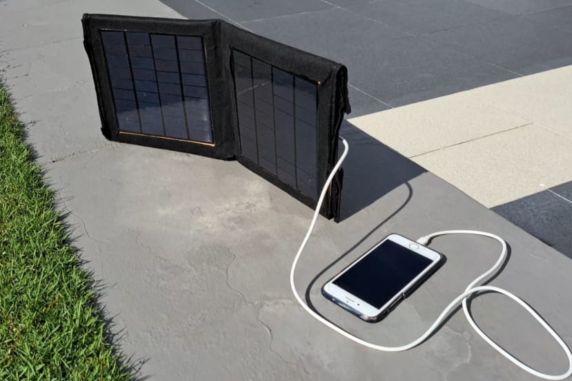

Figure 1: The final product in action!
Now that we enjoyed this little teaser, let us get into action! First, let's take a look at the schematic of the entire charger kit as well as the parts and tools list.
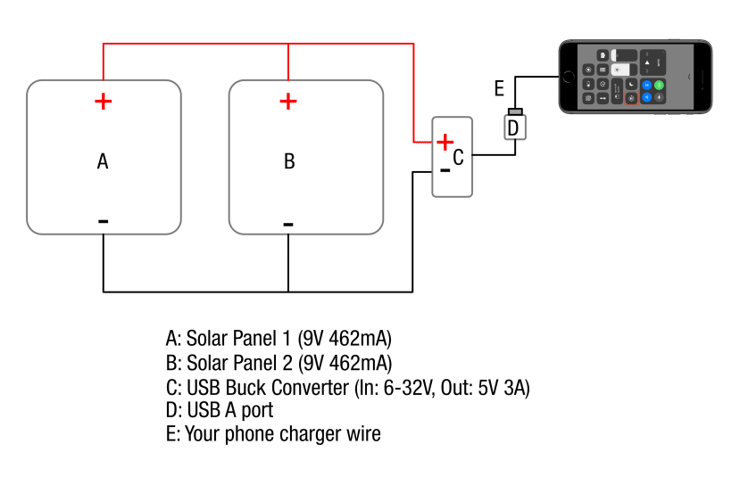
Figure 2: Schematic.
|
Item |
Supplier [URL] |
Description |
QTY |
Alternatives |
|---|---|---|---|---|
|
Solar Panels |
Cytron [link] |
Solar Cell/Panel 9V 467mA (4.2W) Wire Soldered |
2 |
Ali Express (9V 467mA ; Same product) Amazon (requires soldering) |
|
USB Buck converter |
Shopee [link] |
DC-DC Converter Module input 6V~32V to 5V~12V USB Step Down Power Output Adapter |
1 |
Ali Express (Same product) Amazon (Note that the input range is 8-35V) |
|
Insulating tape |
RS (134-7319) |
RS PRO Black PVC Electrical Tape, 38mm x 20m |
As required |
- |
|
Velcro |
RS (890-4180) |
RS PRO Black Hook & Loop Tape, 50mm x 5m |
As required |
- |
|
Stranded Wire |
RS (168-1559) |
Hook Up Wire, 22AWG Stranded (7X30), Pvc Insulated, Ul 1015 Up Wire, 22AWG Stranded (7X30) |
As required |
- |
|
Terminal Block |
RS (464-9744) |
RS PRO 12-Way Non-Fused Terminal Block, 24A, Screw Down Terminals, 2.5 mm², Free Hanging |
1 |
- |
Table 1: Parts list.
Additional parts which you can source relatively simply: Carboard, double-sided tape, cable ties, mounting board, recycle bags, art glue
|
Item |
Supplier [URL] |
Description |
Qty |
Alternatives |
|---|---|---|---|---|
|
Multimeter |
RS (161-1625) |
RS PRO RS-660 Handheld Digital Multimeter |
1 |
- |
|
Wire Stripper |
RS (540-1509) |
RS PRO 155 mm Wire Stripper, 0.2mm → 0.8mm |
1 |
- |
|
USB Tester |
Shopee[link] |
KWS-MX18 10 in1 Digital LCD Display USB Tester Voltage Current Tester Power Meter Timing Ammeter USB Charger Tester Dete HOT1 |
1 |
|
|
Crocodile test lead |
RS (888-3759) |
Mueller Electric Test Leads, 7A, 300V, Black, Green, Red, White, Yellow, 300mm Lead Length |
1 |
- |
Table 2: Tools list.
As you might have noticed, some parts are obtained in my local market due to the cheaper cost. However, in case these parts are not available in your country, I have provided an international alternative. When browsing through these alternatives, keep in mind the preferred specs. In addition, take note of the following tips:
- Unless you are wiring the solar panels in series (which I do not recommend since this means the current will be less), the solar panel has to be at least 5V and above. 8V and above would be the safest bet. The USB buck converter then steps down the voltage to 5V and provides a constant 5V at the USB output. This is because a standard USB supplies 5V of electricity, and hence our phones are made to accept 5Vs of electricity while charging.
- To be error-proof, when choosing a USB Buck converter, be sure that the voltage supplied by the solar panels fall in the input voltage range of the USB Buck converter. For example, the solar panels that I have chosen were 9V, and hence the 6V to 32V range is suitable for our application.
- The output current from the solar panels should be at least 600mA. Anything lesser than that might mean that the phone either doesn’t charge or charges ridiculously slowly. Hence, the recommendation is to wire the solar panels in parallel so we can add up the current. My current setup theoretically provides 924 mA of current. Anything larger than 1.5A might be unnecessary as most smartphones only charge with 1A.
Testing
The very first step is to perform a temporary connection to test the electrical characteristics of the solar panel. You should perform this test as soon as you receive the parts so that you can return and exchange any faulty parts if necessary.
First, connect the positive ends (red-coloured wire) of the solar panels using one end of the crocodile clip, and the other end of the crocodile clip onto the positive test lead end of the multimeter. Do the same for the negative terminals. Then, measure the voltage and current.

Figure 3: Wiring for testing the solar panels
Note: If you do not know how to use a multimeter, here's a video:
Video 1: Multimeter basics.
Here is my setup and the numbers I got
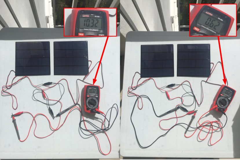
Figure 4: Test setup for solar panels.
About 10.3 V and 620 mA under a relatively strong sun, good numbers!.
To test the USB buck converter, simply replace the multimeter end of the crocodile clip with the appropriate terminals of the USB Buck converter, then connect a USB tester to the USB female end of the buck converter, followed by your phone charger cable and then your phone.

Figure 5: Test setup for buck converter.
I measured about 4.9V and 532 mA, a fairly reasonable performance. The drop in current from the theoretical maximum of 924 mA to 532 mA is pretty much expected. It can be caused by a multitude of reasons, which we will not dive into detail. But more importantly, this just means that our parts are all working as expected. We can now relax and move on to package it into a little nice product.
Building
Solar panel module
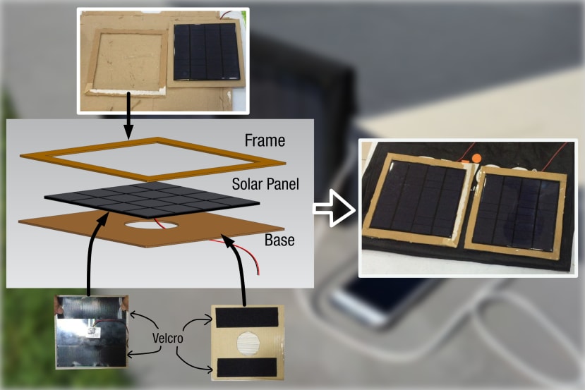
Figure 6: Constructing the solar panel module
To start we need to create solar panel modules. Cut out some carboards to be used as the frame and base as shown in Figure 6. I have cut out a hole at the centre of the base to allow the wires to pass through. I used velcros to adhere the solar panel to the base and some art glue to adhere the frame to the base. Use your best judgment for the sizes of the base and frame. Repeat the same steps for the other solar panel.
Dressing the solar panels up
We now want to "dress up" these solar panel modules to create our final structure. The most environmentally friendly and cost-saving method is to use recycled bags. I used a black recycled bag because I think it looks the most aesthetic.
There is no one right way to dress them up and it all depends on the size of the recycled bag you have and your own creativity. Nevertheless, I will show you how I dressed them up.
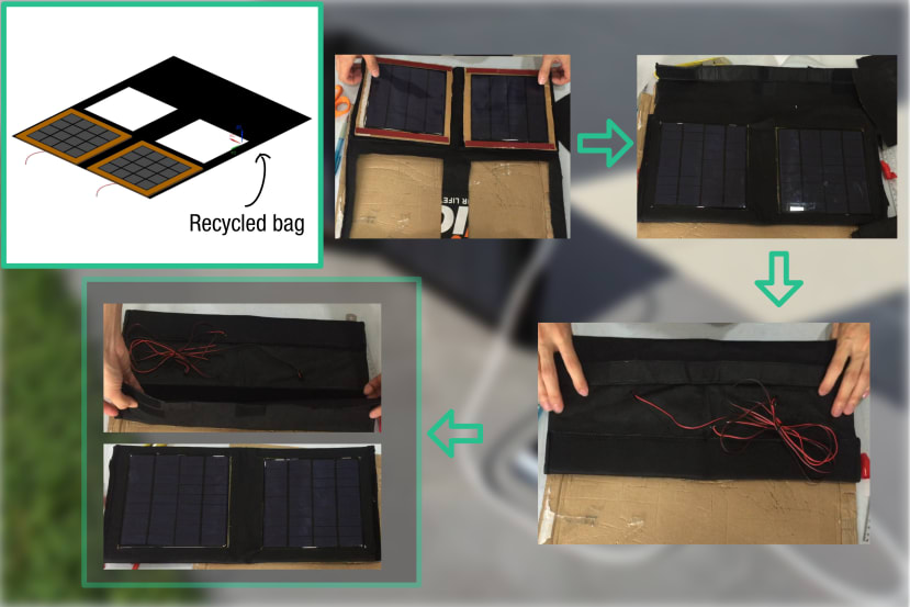
Figure 7: Dressing the solar modules up.
Measure and cut the recycled bags up as shown in Figure 7. I purposely left solar-panel-sized holes in the middle so that when the recycled bag is folded the solar panels are visible. Remember to also cut the back of the recycle bag such that wires from the solar panels can protrude out. I used velcros to attach the back of the solar modules to the recycled bag. To attach the front of the frame to the recycled bag, I used double-sided tape. Again, there is no one right way to do it, I am just simply showing what I did.
You should now have a foldable solar panel kit with wires coming out at the back.
Wiring
Now we are going to do a little electrical wiring to connect the wire terminal ends of the solar panels to the terminal ends of the buck converter. We are also going to create a nice little housing for all these wiring and connectors.

Figure 8: Wiring diagram.
The first thing we can do is connect the wires from both solar panels to the wires from the buck converter with the help of the terminal block. To wire the solar panels in parallel, the trick is to put the positive ends of the wires from solar panels 1 and 2 into one terminal end, and the negative ends of the wires from solar panels 1 and 2 into the other terminal end. Then, connect the positive and negative terminals of the buck converter according to the right terminals on the other side of the terminal blocks. (Figure 8 should be self-explanatory)
If you are using terminal blocks or doing wiring connections for the first time, I highly suggest watching these tutorial videos. There is also a trick on how you should bend the exposed terminal ends of the wire before placing it into the terminal block, which is covered in these videos.
Video 2: An introduction to different types of terminal blocks and how do they work for those curious cats. You could just skip to video 3 if you are in a hurry.
Video 3: This video will teach you everything you need to know for this portion of the project.
Video 4: You might also need to learn how to use a wire cutter if this is the first time you are doing it.
Housing the wires
Yay! We have completed the wiring process. Now onto the last part, which is to house the wires so it looks a bit more aesthetically pleasing. Before we do anything, I highly suggest you use your multimeter to do a continuity test to make sure the terminal blocks are working fine. Also, you can try placing the solar kit under the sun, and then plug in your phone to see if it is charging.
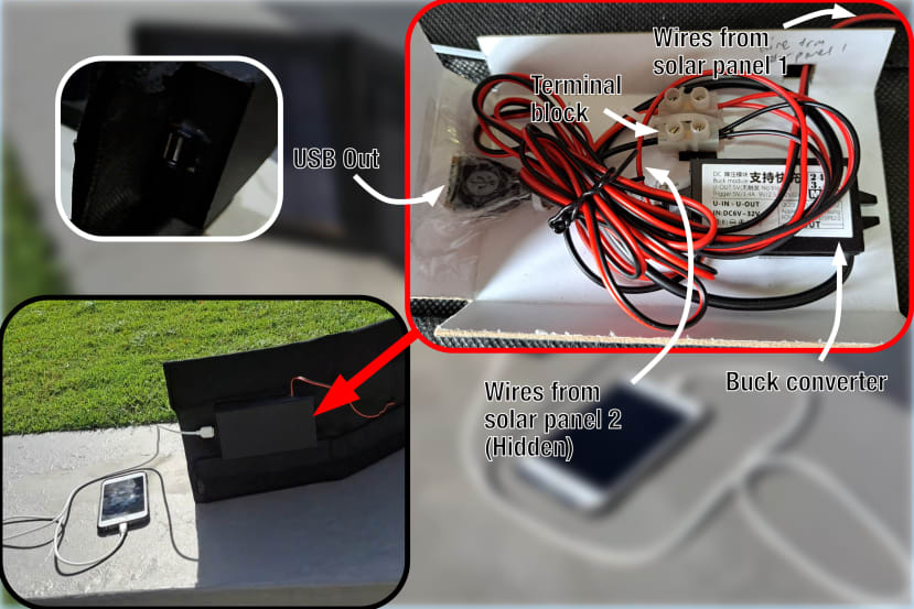
Figure 9: Housing the wires.