Quadrature Encoder Basics Part 2: Practice
Follow article Dave from DesignSpark
How do you feel about this article? Help us to provide better content for you.
Dave from DesignSpark
Thank you! Your feedback has been received.
Dave from DesignSpark
There was a problem submitting your feedback, please try again later.
Dave from DesignSpark
What do you think of this article?
After learning a few things about the quadrature encoders in the previous article – Encoder Basics Part 1 - Theory– let's try to detect the signals they emit!
What you will need:
- Stepper or DC Motor with incremental quadrature encoder
- 8-pin encoder connector cable
- Arduino board (in this case we are using Arduino UNO R3)
- LCD Screen to display results (in this example Sainsmart 4x20 chars)
- Breadboard and Dupont cables
First of all, we will need to strip one side of the 8-pin encoder cable.
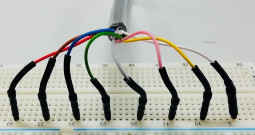
Now that we have a clear image of the 8 pin cables we should identify them. If you are using an igus encoder cable they are as following:
A and B channels on White and Green
A/ and B/ inverted channels on Brown and Yellow (used for filtering)
Index channel N and N/ on Pink and Blue (emits one signal per rotation of the motor used for homing)
Ground on Grey
VCC on Red (5VDC)
We know that the Arduino UNO has a 5VDC output pin and that should be adequate to power the encoder, of course using an external power supply adds stability and less fluctuation but let's keep it as simple as possible.
Wiring the encoder to the Arduino UNO
As stated above the connections will be as following:
Encoder – Arduino
| VCC | Red | 5V |
|---|---|---|
| GND | Grey | GND |
| CH B | Green | Pin 2 (important as we will use the pin as an external interrupt) |
| CH A | White | Pin 4 |
LCD Screen – Arduino
| VCC | Red | 5V |
|---|---|---|
| GND | Green | GND |
| SDA | Blue | A4 |
| SCL | Purple | A5 |
And here is a block diagram:

After connecting the Arduino to the PC, open the Arduino IDE with a new sketch.
From the menu bar select: Tools > Board > Arduino Genuino UNO (or your respective board). And from the same tab, the port that you have your Arduino connected to.
Writing the code
Let's explain some basic parts of the code. We will first include the libraries needed:
#include <Wire.h>
#include <LiquidCrystal_I2C.h>
Display the home screen on the LCD for 1500ms:
 lcd.home ();
  lcd.print("Encoder Tester.");  // Print a message to the LCD.
  lcd.setCursor( 0, 3);//Set the cursor to line 3 (first line is line 0)
  lcd.print("Please plug encoder.");
  delay(1500);
Attach the RISING interrupt:
 attachInterrupt(0, runEncoder1, RISING );
// encoder pin on interrupt 0 >>(pin 2 on arduino)
Because of the nature of the LCD whenever a character is printed, it stays on the LCD until is overwritten by another character (including space). The count of steps will increment and decrement 500 ticks per motor rotation.
So if the motor moves forward half rotation the LCD will print 250 steps and if the motor moves backwards for half rotation the ticks decrement to 0-ticks but the LCD will actually show 150 as last two numbers were printed but not refreshed.To solve this "bug", we will refresh the LCD by printing spaces every time that the value of the character decreases.
 lcd.setCursor ( 8, 2 );        // go to the 2nd line
  lcd.print(Pos1, DEC);
   if (Pos1 < 100000) lcd.print(" ");
  if (Pos1 < 10000) lcd.print(" ");
  if (Pos1 < 1000) lcd.print(" ");
if (Pos1 < 100) lcd.print(" ");
if (Pos1 < 10) lcd.print(" ");


  lcd.setCursor ( 0, 3 );        // go to the fourth line
  lcd.print("                    ");
Last but not least, we should set the interrupts routine:
void runEncoder1()
{
 if (digitalRead(encoder1PinA) == digitalRead(encoder1PinB))
   encoder1Pos++;    // count up if both encoder pins are HIGH on pin change interrupt
 else
   encoder1Pos--;    //count down if pins are HIGH and LOW
}
Having in mind the encoder sequence from the datasheet:

In a clockwise (positive) rotation, if we attach the interrupt to channel A, the interrupt will be triggered by the HIGH signal. The Arduino will check if channel B is HIGH as well, which is not, and the Arduino will record -1 encoder steps which is wrong.
So the interrupt should be attached to channel B, when channel B goes HIGH, Arduino will check channel A which will be also HIGH and it will recond +1 encoder steps.
If the motor moves counter-clock wise, thus the sequence is reversed, when channel B goes HIGH and triggers the interrupt, Arduino will check channel A which will be LOW and it will register -1 encoder steps.
How are these signals used in automation projects?
With low-end generic controllers, we would command the stepper motor to move one rotation which equals 200 motor steps. Only channels A and B are used.
After the command was sent and completed by the motor, we would check if the encoder steps are on 500.
If a command of 200 motor steps is sent and we get 500 encoder steps feedback, motion was completed successfully.
If on the other case we get less encoder steps, it means that motor lost some steps due to excessive load, obstacles etc. thus we will instruct the motor to be disabled (de-energised) and an error to be emitted through a red LED for example.
With high end controllers like the igus D1 Dryve, channels A, B are used for feedback, N can be used for homing if needed, A/, B/ and N/ for filtering.
With the D1 Dryve when a motor with an encoder is used, we can enable closed loop.
Closed loop is a field-oriented control with sinusoidally commutated current-vector control meaning that the motor current is controlled on the go using the live feedback from the encoders in relation to the load.
For example, if the load increases the controller will increase the supplied current to the motor and vice versa. This eliminates the posibility of losing steps thus losing position which is a main problem when using stepper motors.
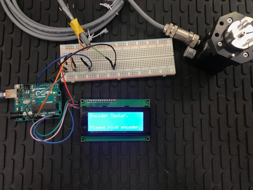
Here are pictures of the completed project:

More information about the motor and the D1 Dryve controller?
More information about encoders?
Full Code?
(Look at the attachments below.)
In a new series of articles, I will start exploring motor controllers for various types of motors and the different control modes they have.
Thank you for reading, please comment your thoughts/ questions at the comment section!
A.B.