Detecting Lightning with an Arduino
Follow article
 Dave from DesignSpark
How do you feel about this article? Help us to provide better content for you.
Dave from DesignSpark
Thank you! Your feedback has been received.
Dave from DesignSpark
There was a problem submitting your feedback, please try again later.
Dave from DesignSpark
What do you think of this article?
This post takes a look at interfacing the novel AS3935 lightning sensor with an Arduino.
The AS3935 works by detecting radio frequency emissions generated by lightning activity, and uses algorithms to distinguish these from man-made “disturbers” and to calculate the energy from strikes. From which it's able to then estimate the distance to the head of the storm over a 1–40km range.
The manufacturers, AMS, say that the AS3935 can be used “to protect both humans and equipment from harm by providing early warning of impending danger.” Suggesting that potential applications include use in hiking, at marine and sporting events, and with telecoms equipment, uninterruptible power supplies (UPS) and power conditioners etc.
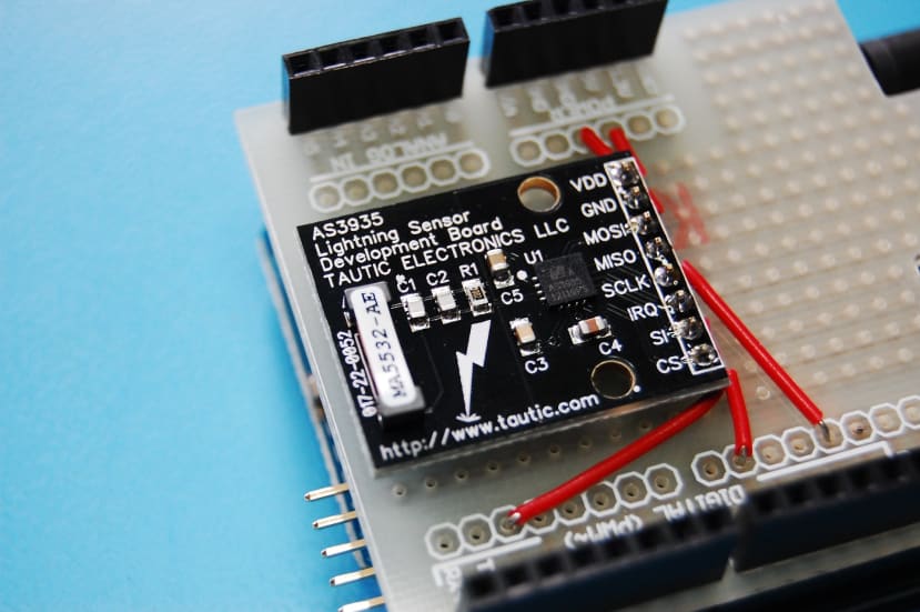
Breakout board
The sensor is housed in a 4x4mm package and draws only 60uA in listening mode, and will issue an interrupt when lightning is detected and can be interfaced using I2C or SPI.
The compact MLPQ-16 packaging is great for building into an end user product, but is not particularly friendly for experimenters and prototyping with only access to simple tools. Fortunately, Tautic Electronics have produced a development board that includes the required antenna and passive components.
Arduino library
The comprehensive datasheet provided includes all the information required to write your own code to interface with the AS3935, but this has been made much easier for Arduino users thanks to a library from Raivis Rengelis. This includes functions for:
-
power up/down and reset
-
calibrating the antenna
-
getting/setting the noise floor
-
getting/setting the number of strikes before interrupt is raised
-
returning the source of the interrupt (noise, disturber or lightning)
-
returning the distance to the head of the storm
The library also comes with an example sketch.
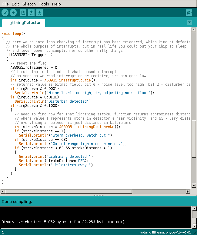
The main loop for lightning detection is very simple and the output from running the sketch can be seen below.
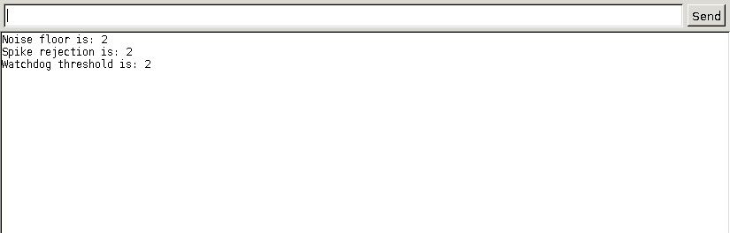
Not surprisingly, this isn't particularly exciting. Nor will use of the sensor ever be unless a lightning storm is nearby!
Note that with Arduino boards other than a Mega 2560 it may be necessary to change some pin definitions. When using an Arduino Ethernet I chose to use pin 9 for SPI Chip Select since 10 is used by the Ethernet chip, and pin 2 was used for interrupts since this is int.0 on the board.
A useful design

Here in the UK we don't get lightning storms that often and for the best chance of catching one the detector really needs to be powered up 24/7.
In order to turn into a useful design I'll probably house the Arduino and shield in an enclosure so that I can forget about them without fear of damage. Using the example sketch to develop one that logs data to a platform such as Cosm, thereby enabling strikes and their intensity/distance to be graphed over time.