Building a Retro 32-bit Core Memory for Arduino
Follow article
 Dave from DesignSpark
How do you feel about this article? Help us to provide better content for you.
Dave from DesignSpark
Thank you! Your feedback has been received.
Dave from DesignSpark
There was a problem submitting your feedback, please try again later.
Dave from DesignSpark
What do you think of this article?
Assembling an Arduino shield kit that demonstrates how computer core memory works.
Building on the work of Ben North and Oliver Nash at corememoryshield.com, Jussi Kilpeläinen has come up with a kit for a core memory Arduino shield – a project that he describes as “hilariously impractical”.
Image by Konstantin Lanzet shared on Wikipedia, licensed under the Creative Commons Attribution-Share Alike 3.0 Unported license.

For a year or two, my computer at work has had this picture of ferrite core memory for its wallpaper. It was one of those images I had come across on Wikipedia, while searching for something else, and had liked and saved. I understood it was an early type of computer memory but beyond that knew little or nothing about it.
Then my colleague pointed me at a DIY kit for building a 32-bit ferrite core memory made by Jussi Kilpelainen in Finland and I thought it would be fun to build and find out a bit more about this pioneering early computer technology. Little practical purpose but gives an insight into the development of computers without which the world would be a very different place.
Magnetic-core memories were the predominant form of computer memory from the mid-50s until the mid-70s. They work by storing information into the magnetic field of a ferrite core.
Each ferrite ring, or core, can be magnetized in either the clockwise or anti-clockwise direction and can therefore store one bit of information. The value of the bit stored in a core is zero or one according to the direction of that core's magnetization. The direction of the magnetization in a core can be set by passing an electric pulse through the wire threaded through it - one direction will result in clockwise magnetisation, the other anti-clockwise, thus storing a one or a zero. Another wire through each core, the sense wire, is used to detect whether the core changed state.
Core memory is non-volatile, meaning that it preserves its contents even when power is turned off. Also, the process of reading the memory destroys its contents, so that every read must be followed with a write if you don’t want to lose these. The disadvantages of this type of memory are that it is power-hungry, requires a lot of space and needs to be protected from strong magnetic fields.
One of the early uses of core memory was in a real-time aircraft tracking system developed by the Massachusetts Institute of Technology in 1953 called Project Whirlwind. Early commercial use of Core Memory in the mid-1950s was in jukeboxes.
Assembling the kit
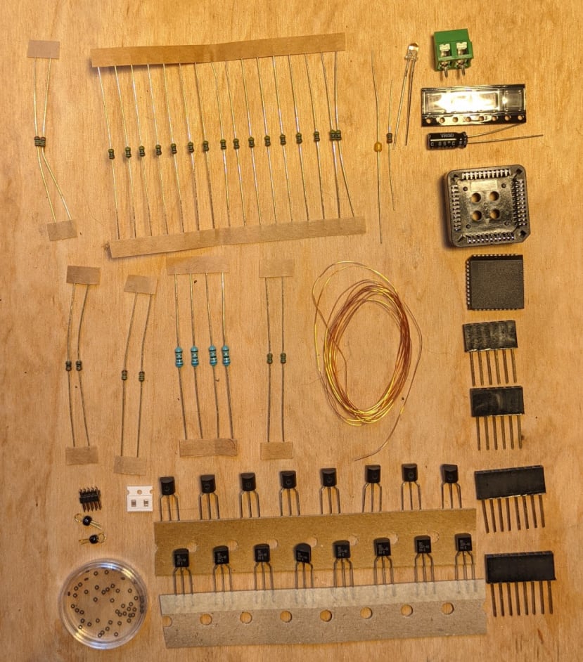
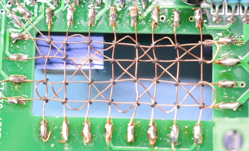
I decided to tackle the most difficult part of the kit first, threading the tiny ferrite beads onto the copper wires and soldering them in place.
Starting with the vertical wires, I soldered one end in place, threaded eight beads on to it and then soldered the other end, while trying to keep it as taught as possible. After I had completed this I read a good tip for taping the wire down before soldering it, using Kapton tape
(436-2762)
to help keep it taught. A pair of needle-nose tweezers
(054-9628)
was an invaluable tool during this process.
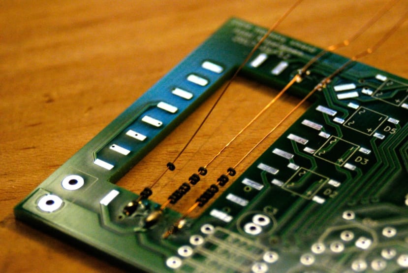
The next job was to thread the horizontal wires through the beads, making sure the beads were correctly oriented – each bead being diagonal to the wire and at right angles to the bead next to it, as in the illustration above.

Finally, I threaded the sense wire, again following the illustration where it is the one coloured orange.
Once that was done I breathed a sigh of relief and set about soldering the components in place, starting as ever with the resistors. It was then that I discovered the values for the resistors I had supplied with the kit, did not match the ones in the BOM I was working from. Which confused me somewhat until I noticed that the latest version of the board had been updated to use 5V from the Arduino, whereas the version I had was an older one that had a connector for a 3.3V supply. I checked the date on my PCB, located the corresponding BOM and everything matched up.
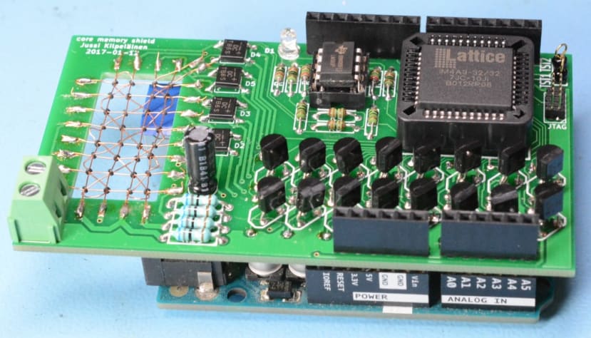
That mystery cleared-up, I started by soldering the resistors on the base of the PCB.

The board is quite compact with components close to each other, including 4 SMD bridge rectifiers and two SMD resistors that solder between pins on the underside of the PLCC socket – so it was not a completely straight forward build and took some time to complete.
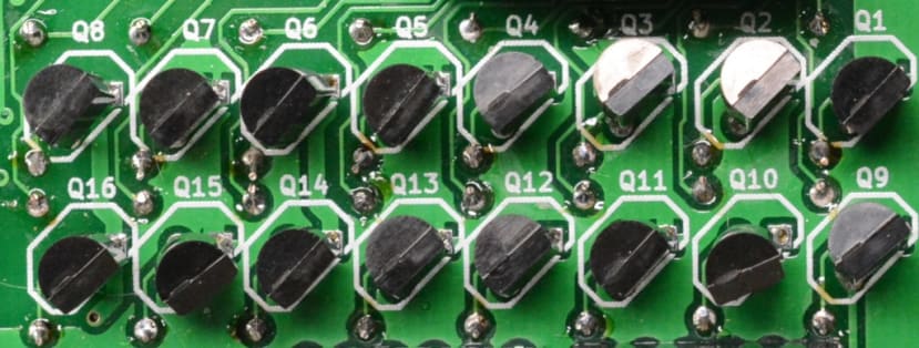
The driver transistors were also quite tricky; as well as making sure I did not mix up the PNP and NPN transistors, the resistors on the underside of the board do get in the way a bit but as long as you use a soldering iron with a fine tip it is do-able with care.
Luckily the documentation is good and clear, as long as you make sure you are reading the version for the iteration of the board that you are working on!
Arduino
The creator of the kit recommends using an Arduino UNO (715-4081) , although also cautions that the large USB B socket can sometimes interfere with the underside of the shield. I fixed a small piece of insulating tape over the top of the socket, to make absolutely sure it did not short out anything on the base of my shield.
I also tried an Arduino Leonardo (761-7324) that has the much smaller mini USB connector but did not have any luck getting it working with that.
I needed to supply 3.3V to the connector on the shield, which I did using my bench power supply.
The Lattice CPLD (Complex Programmable Logic Device) included with the kit comes pre-programmed, so all I needed to do to get my memory working was to upload the provided sketch to my Arduino, using the Arduino IDE.
Testing
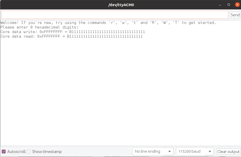
Once the sketch was uploaded I opened the Serial Monitor. I was greeted with the message “Welcome! If you're new, try using the commands 'r', 'w', 't' and 'R', 'W', 'T' to get started.” So it at least looked like the core memory was up and running and my “crochet had not been in vain.
I tried a simple write to the memory by typing “WFFFFFFFF” which returned the message
“Core data write: 0xFFFFFFFF = B11111111111111111111111111111111”. I could confirm this had in fact been written to the memory, by typing R for Read and at once saw the following:
“Core data read: 0xFFFFFFFF = B11111111111111111111111111111111 “
So, everything seemed to be working.
As I said above the memory is persistent so, if I powered down the shield, then turned it on again and read it, it should give the same message – which it did. I also discovered that waving a fairly strong magnet over the core would erase or at least disrupt the memory.
Conclusion
This project is, as its originator says is “hilariously impractical”, but it has been educational and I now understand a little more about computer history — what that interesting thing on my PC wallpaper is and marvel at the skill and dexterity taken to thread all those ferrite beads.
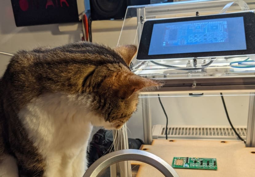
On a side note, it was the first time I had used the Pi Camera booth to record a project and I was pleased with the resulting time-lapse video — obviously Vince the cat supervising proceedings helped enormously.