Assembling the RepRap Ormerod
Follow article
 Dave from DesignSpark
How do you feel about this article? Help us to provide better content for you.
Dave from DesignSpark
Thank you! Your feedback has been received.
Dave from DesignSpark
There was a problem submitting your feedback, please try again later.
Dave from DesignSpark
What do you think of this article?

Putting together No. 5 of the 500 limited edition RS RepRap Ormerod 3D printers.
I was one of the lucky few who received a limited edition RepRap Ormerod in RS livery and this post takes a look at the process of assembling the printer.
Important note: this should not be used an an assembly guide and the official documentation should be used instead, as this is far more complete and much less likely to have errors!
Construction
The kit arrived in a surprisingly small box, but upon opening it became clear that it was very densely packed, with components neatly organised into many smaller packages.
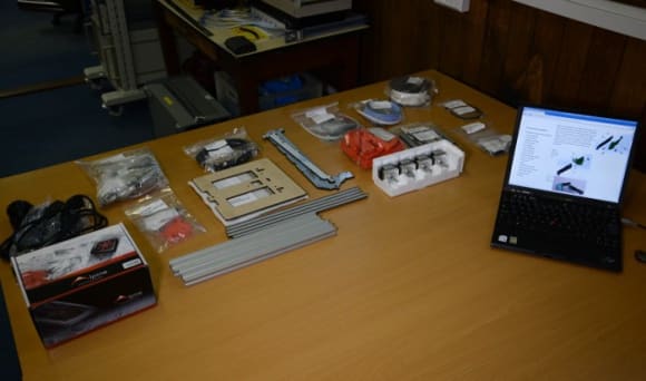
With all the parts laid out and tools at hand, it was time to make a start on construction!
The first sub-assemblies that are put together are for either end of the Y axis. These can be seen below and each are made up of one printed part plus one laser cut one.

One of these has an idler bearing fitted and the other will have the Y axis motor attached.
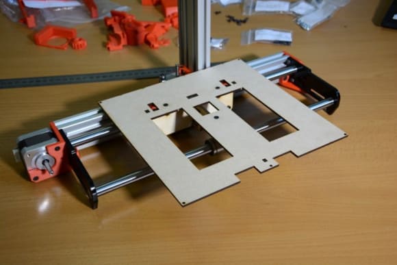
Next the Y axis frame is put together using the ends, together with an aluminium extrusion, smooth rods and linear bearings. This is what the printer bed will travel along.

The Z axis is put together next and this comprises of another section of aluminium extrusion, printed mounts, another smooth rod and more linear bearings.

The Z axis needs to be set at a specified distance along the Y axis and obviously needs to be at a right angle to it (a plastic set square is included in the kit!)
Now that the frame is assembled it's time for the Y carriage. This is made of laser cut parts which are screwed together and attached to the linear bearings with printed clamps.
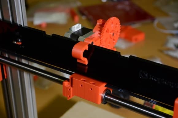
The pulley can then be attached to the Y axis motor and the drive belt fitted.

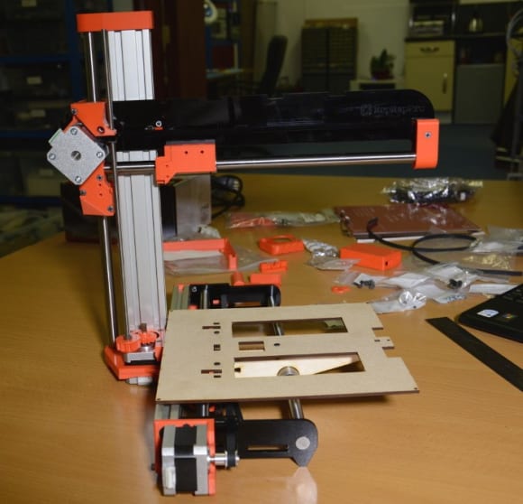
Next the X axis is assembled. This comprises of two laser cut acrylic parts, along with a printed X carriage, mounts and brackets, and of course the remaining smooth rod and linear bearing.
Printed drive gears are fitted to the Z axis motor and a threaded rod which passes through a nut, which together enable the the X axis assembly to be raised and lowered.
The drive belt can then be fitted for the X axis, and the extruder drive put together and attached to the X axis plate.
The last major assembly to be put together is the hot end. This comprises of an airflow system made up of a fan, heatsink, printed duct and aluminium cooling block, plus a Bowden tube, and of course the nozzle and heater block. The final components to be fitted are a cartridge heater and thermistor.

The electronics are housed in a neat printed and laser cut enclosure which is attached to the Y axis.

Pre-made wiring looms are fitted next, along with the 12v power cable.
The heated bed stack comprises of an aluminium heat spreader plate which sits on top of the heater PCB, and on the underside of which a cardboard insulator is attached. The bed also has a thermistor for temperature control and this is inserted into a hole in the middle of the PCB.

Next the wiring harness for the heated bed is made up using the supplied ribbon cable and connectors. The bed is then fitted and the harness routed between this and the electronics.
The print surface is a sheet of glass covered in Kapton tape. At each corner and under the tape are pieces of aluminium foil which will allow a proximity sensor to measure the distance of the nozzle from the bed — or rather, the Z position.
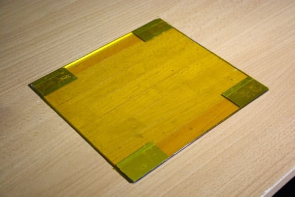
The print surface is attached to the plate with bulldog clips.
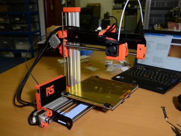
Finally, the printer is connected to the power supply and is ready for commissioning!

Initial thoughts
With its use of aluminium extrusions and a number of laser cut parts, the Ormerod is much simpler to construct than previous RepRap designs which used threaded rods for the frame, and overall it's a smart machine that doesn't take up a lot of room on a desk or workbench.
I did discover a few errors in the documentation, such as small assembly steps being omitted, but these appear to have since been rectified.
Putting together a RepRap is definitely one of those things where you want to pay close attention to the instructions, and ensuring that you have the required tools and components at hand for each stage should make things go a lot smoother. Where screws are passing through a printed part and are not “self-tapping” (e.g. a nut is being used), it's important to clean up screw holes with a file.
The total time taken to assemble the printer was somewhere in the order of 10-12 hours, but along with the documentation errors I did make a few small mistakes of my own. With the updated documentation and due care and attention, it should take less time that this — perhaps much less if you carefully prepare, don't rush and have a day free of distractions!
And now, on to commissioning... read this blog