Why do we need airflow - System resistance and overcoming back pressure
Follow article
 Dave from DesignSpark
How do you feel about this article? Help us to provide better content for you.
Dave from DesignSpark
Thank you! Your feedback has been received.
Dave from DesignSpark
There was a problem submitting your feedback, please try again later.
Dave from DesignSpark
What do you think of this article?
System Resistance – Overcoming Back Pressure
In previous articles on why we need airflow, maintaining a healthy environment indoors and providing cooling for processes generating heat were discussed. These are separate reasons for delivering air to a space or through a piece of equipment, however they can be combined to form the basis of air conditioning. Whether the need for air movement is to provide a healthy environment, for personal comfort or to maintain a process temperature, there should be a defined path along which the air will take. Any components placed in the airflow path are obstructions that will impede its flow.
Particulate Filtration

The air that surrounds us in normal everyday life contains small particles of airborne dust. The amount of airborne dust will depend on the environment, the activity that is taking place within the environment and the prevailing weather conditions. In Summer, there is usually less rain, ground conditions tend to be drier and the air is warmer which has a number of effects on the environment.
Dry ground conditions mean that dirt and debris on the ground become lighter as they lose water through evaporation. Grasses, trees and flowers are more active during the spring and summer months when they naturally produce pollen in order to propagate. In addition to this, road and rail transport produce particulates as a result of burning fuel, brake dust and component wear.
When combined with wind and thermal airs the smaller lighter particles of dust and pollen become airborne and can become carried into buildings and equipment located outdoors. To prevent this happening there are a number different filter designs that block the passage of dust/particulates whilst allowing the air to pass. The method in which dust is arrested can vary and as the filters gradually clog up with dust, the free area available for the air to pass decreases, which increases the resistance to flow. As the resistance of the filter increases the pressure required to force the air through the filter also increases.
Heat Exchangers
When the temperature of the incoming air is too high or too low we are able to remove or add heat as required using a fin and tube heat exchanger. Similar in construction to a car radiator grille, thin metallic fins are thermally bonded to tubes (the coil) which carry a hot or cold fluid. The fluid passing through the coil can be a liquid refrigerant / water or it can be a hot gas. The fins increase the effective surface area of the heat exchanger making the exchange of hot or cold energy from liquid to air more efficient. This type of heat exchanger also makes use of a fan to force large quantities of air through it increasing the effectiveness of distributing the hot or cold air.

There are a number of variables that affect the heat exchange performance including the number of coil rows passing through the fins, the depth of the heat exchanger as well as the fin spacing. More rows of coils and a smaller fin spacing deliver a greater fin surface area which provides a higher heat transfer from the heat exchanger. A greater number of coil rows and a closer fin spacing also creates a more tortuous air path and adds greater resistance for the air to overcome. The successful design of a heat exchange coil will be a balance of heat energy output, the space available, efficiency of the heat exchange process, the pressure required to push the air through it and the maintenance needed to keep it operating at peak efficiency.
Ducted Building Heating and Ventilation Systems
To maintain a healthy indoor environment we need clean, fresh air to be supplied at a comfortable temperature whilst removing stale air laden with moisture, CO2, Nitrous oxides, volatile organic chemicals as well as other pollutants that build up indoors. Air is drawn in from outside via a mechanical ventilation unit which can contain a number of additional components to the filter and heat exchanger detailed above.
Some ventilation systems simply extract stale air from the building and allow the leaks in the building structure to provide the fresh air (Mechanical Extract Ventilation – MEV). Some ventilation systems take the fresh air from outside and positively pressurise the building using the leaks in the building structure to exhaust the stale air (Positive Input Ventilation - PIV).
Both of these systems involve drawing fresh air into the building and forcing the stale air out. In the warmer months of the year this may be desirable as the ambient temperature outside may be lower than inside and the building may benefit from some cooling. During the colder months this may not be desirable as the air inside may have been heated to maintain a comfortable environment. During the heating season rejecting warm air from the building and replacing it with colder external air may cause discomfort and will require more heat output from the heating system within the building.
Heat Recovery Systems
The process of rejecting stale air in the building to the outside will also reject any heat energy held in the air. Whether in the winter (the air would be heated) or in the summer (the air would be cooled), the energy used to maintain the temperature indoors will be wasted by exhausting it to the outside. To minimise the impact on the amount of heat energy wasted, a heat recovery cell or heat wheel can be used to reclaim some of the heat energy as the air is exhausted from the building. This heat energy is then imparted to the incoming supply air to minimise waste and demand on the heating and cooling systems in the building.
Heat recovery systems come in a variety of forms and as with heat exchangers there needs to be a balance between the efficiency of the heat exchange rate and the pressure needed to overcome by passing the air through it. This type of system is called a Mechanical Ventilation System with Heat Recovery (MVHR)
Other components involved in an air distribution system - Ducts / splitters / bends / terminal devices
Whether the ventilation system is an MEV or MVHR it will have a defined air flow path containing ductwork, duct bends and splitters, terminal devices, dampers and trickle vents and to extract stale air and deliver fresh air. Each of these components will create a resistance to flow which will need to be overcome as well as resistance that is created inside the MEV or MVHR unit described above. These are collectively known as the external resistance of the system.
Contamination control - Odour removal / Gas Neutralisation / Fine particulate filtration
Hazardous areas involving the use of chemicals, the presence of toxic fumes or fine particulates may require specialist filtration to protect operatives from harm.
Active Carbon filters are used to absorb chemicals and odours from the air, neutralising harmful vapours and gasses. Carbon provides a large surface area in which to absorb the chemicals however they are usually densely packed which provides a high resistance to air passing through them
Fine filtration can be used to arrest minute particulates such as asbestos, pharmaceutical products or silicate dust that may cause long-term health damage if breathed in.
Fan Positioning – Air path
Where we position the fan and the air path will also have an effect on the pressure it will be operating against. If we consider the example of a small axial compact fan being selected to provide air into an enclosure that contains electronics that require cooling, we could position the fan to blow into the enclosure or to draw air out of it.

Where we are blowing into the enclosure we create a turbulent airflow with the air moving in lots of directions and covering the majority of the surfaces of the components. The air passing over the fan is cool but the turbulence inside the enclosure means that the fan has to overcome a higher air pressure to get the air through the application and is noisier.
If we were to draw the air through the application the airflow is more laminar meaning that some of the surfaces of the components do not see the cool air flow. The air passing over the fan is warmer and the laminar flow means that there is less pressure and less noise in the application, however, the components in the application may run hotter as a result.
Combining Airflow and Pressure – Fan selection
When considering the most appropriate fan to deliver the required volume flow (whether this is to provide a healthy environment or for process cooling), we need to know how much resistance to flow in terms of back pressure the fan will need to overcome. When we know the volume flow – m3/hr - and pressure – Pa (N/m2) – we have a duty point. We can plot the duty point on a fan characteristic curve to ensure that it is suitable to deliver both the volume flow against the system pressure.
For example, if we have calculated that our equipment will require a flow rate of 700m3/hr and at this flow rate the air will encounter 450Pa of resistance as it flows through the system. We will need to select a fan whose performance characteristic can meet or exceed this duty point.
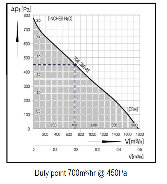
The duty point will need to be either on the maximum performance line or below it. If the duty point was below the performance characteristic and to the left (Shaded area), this would still be an appropriate fan selection to meet the duty.
If the duty point was above and to the right of the characteristic (Unshaded area), it would not be suitable and a higher performance fan would need to be selected.
Summary
In summary, fan selection relies on both the volume flow rate that is required to be moved to maintain a healthy environment or process and the resistance that the air will encounter as it passes through the system or equipment. Combining the flow rate (m3/hr) and the resistance to flow (Pa) we obtain our duty point which is the starting point for selecting an appropriate fan for the application.
For more details including graphics illustrating the points made in this article please download and view the accompanying PDF file.