University of Southampton Students Developing Near-Earth Object Tracking Telescope
Follow project
 Dave from DesignSpark
How do you feel about this article? Help us to provide better content for you.
Dave from DesignSpark
Thank you! Your feedback has been received.
Dave from DesignSpark
There was a problem submitting your feedback, please try again later.
Dave from DesignSpark
What do you think of this article?
 We are a group of 4th year engineering students at the University of Southampton, working on a project to design and construct a telescope capable of tracking and imaging the ISS and other near earth objects.
Parts list
| Qty | Product | Part number | |
|---|---|---|---|
| 2 | Pinion,Gear,1.0 module,1 start, 50 teeth | 521-6979 | |
| 2 | RS PRO Steel RH 32mm Long Worm Gear, 1 Start , 18mm Diam , 16mm Pitch Diam. , 20° Pressure Angle | 521-6890 | |
Who We Are
We are a group of 4th year engineering students at the University of Southampton. The group is made up of 5 aerospace engineering students and 1 mechanical engineering student.
The Project
As part of our degree, 4th year engineering students at the University of Southampton complete what is known as a ‘Group Design Project’ or GDP. Our GDP is PLATO, the Platform for the Autonomous Tracking of Orbits. The goal is to design and construct an automated telescope that is capable of tracking and imaging objects in near earth orbit, specifically the International Space Station. All GDPs have the same initial budget of £850, and therefore cost is one of the greatest restricting factors on our design.
There is currently a large variety of actuated telescopes available to buy from numerous retailers. However, these telescopes are only designed to aim at large known objects with relatively slow rates of movement, for example other planets within the solar system. The part of our telescope that will make it distinct from these commercially available options is the ability to track near earth objects. The ability to track near earth objects will require a balance between speed and precision from our actuation system, as due to their proximity to earth the objects we wish to track will move far more quickly across our vision, resulting in us requiring a greater actuation speed that most telescopes. We have therefore designed our own optical tube assembly and mount, which will be accompanied by in-house tracking software.
The Design
Actuation
The telescope moves on a two-axis altitude azimuth system, allowing us to cover the entire necessary region of sky with a relatively simple actuation system. When designing the actuation system, we had to consider the fact that when high overhead the acceleration needed to maintain tracking of the ISS would be a near infinite value, and therefore we would not be able to observe the target at all angles. We have calculated the required motor accelerations for a range of ISS passes during April 2020, which is our planned observation time. From these calculations we have determined that one of the permanent magnet stepper motors, with 1.8o steps, 0.36Nm torque and 1.68A current draw, available from RS Components. This motor has a maximum speed of 1.5625 RPM when geared, which is suitable to allow us to view more than 90% of passes.
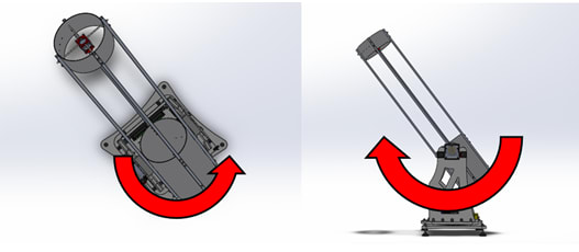
Figure 1 - Diagram to show the axes of rotation. Left azimuth, right altitude.

Figure 2 - Altitude actuation system
The motors will turn worm gears connected to wheels attached to the optical tube and the telescope base. The gears we are using are the RS PRO Bronze 50 Teeth Worm Wheel Gear (521-6979) and the RS PRO Steel RH 32mm Long Worm Gear (521-6890) . These components give a gearing ratio of 50, which with a step size of 1.8° from our motors, gives a resolution of 0.036° which is far smaller than the main cameras field of view. This results in relatively smooth movement throughout the tracking process, despite the use of a stepper motor.
Optical Tube
For the optical tube assembly (OTA) an open section was included in the centre, this was due to both manufacturing constraints and as a method of reducing the overall mass of the OTA. However, this does reduce the overall rigidity of the structure and leaves the mirror less protected from the elements. The section to the rear of the gap holds the mirror cell and is the point of attachment to the mount, and the front section holds the spider assembly, which will contain our primary camera. A slightly unusual prime focus design was selected for our system as this enables a simpler construction and removes the need for a secondary mirror to be included. A prime focus design has the camera placed at the focal plane of the primary mirror, so no secondary mirror is needed to divert the light out to the side of the tube.
Our primary camera has a very limited field of view of only 0.3° in each direction, this is due to the magnification of the telescope. Therefore, to allow for the tracking functionality of our system will have a guidescope with secondary camera attached to the outside of the optical tube. This will have a smaller magnification than our primary telescope, resulting in a far larger field of view and therefore the ability to re-acquire the desired target in the main camera’s view if it becomes lost.
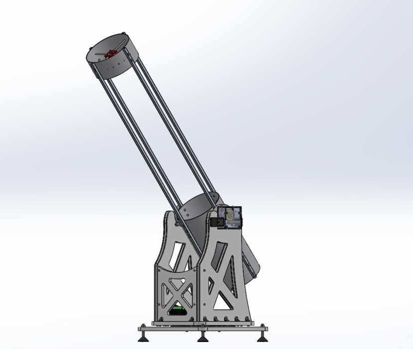
Figure 3 - CAD for the entire telescope, with open OTA design.
The software for the secondary camera will detect objects that move across its field of view and then begin to follow them, attempting to get them aligned with the primary camera. Once acquired by the primary camera, the software will attempt to keep the target object centralised within the main camera’s FOV
Software
Currently the software for our system is at a very early stage. So far, we have created a piece of software that connects to an online orbit database and determines which ISS passes will be visible with our telescope at a given location over a given date range. It returns the time windows during which the ISS will be observable, enabling us to better plan when we will make our observations. The image processing code for our tracking system is also in its early stages. The image processing will be performed using OpenCV and Python. At the moment the software is able to identify objects within a certain contrast range from their background, and can locate the brightest area of a given image. The next stage is to compare locations of objects between video frames and then determine their distance from the image centre, in order to calculate vectors to feed to our actuation system.
Next Steps
Now that the design for our system is complete, we have begun production and assembly of components, the majority of this will be done ourselves as we must operate on a very restricted budget. Testing has already begun for individual components and sub-systems, and photography can begin once the whole system has been constructed. This will also enable the refinement of our tracking code based on practical observations.