The ABC’s of Clamp Meters
Follow article
 Dave from DesignSpark
How do you feel about this article? Help us to provide better content for you.
Dave from DesignSpark
Thank you! Your feedback has been received.
Dave from DesignSpark
There was a problem submitting your feedback, please try again later.
Dave from DesignSpark
What do you think of this article?
What is a Clamp Meter?
This introduction to clamp meters investigates, 'What is a clamp meter?' and more importantly 'What can you do with one?' Understanding the different features will allow you to choose the best clamp meter for your requirements (this is also illustrated by a video at the end of this article).
As the world advances, so does technology and with that electrical equipment and circuitry are becoming more complex creating more challenges when things go wrong for electricians and technicians. These advances, therefore, mean the capability of today’s clamp meters need to be more advanced, but also the skills of the engineers using them, in that they have the knowledge of the latest test methods and troubleshooting challenges.
Originally starting out in the Analog world as a single purpose test tool for electricians, the clamp meter has moved into the digital world and now combines many basic functions found within a digital multimeter (DMM) along with increased accuracy and special measurement features.
Clamp meters can measure large currents, originally these were just ac currents based on the simple transformer action, but then later using “Hall effect” technology to measure dc current (more of that a little later).
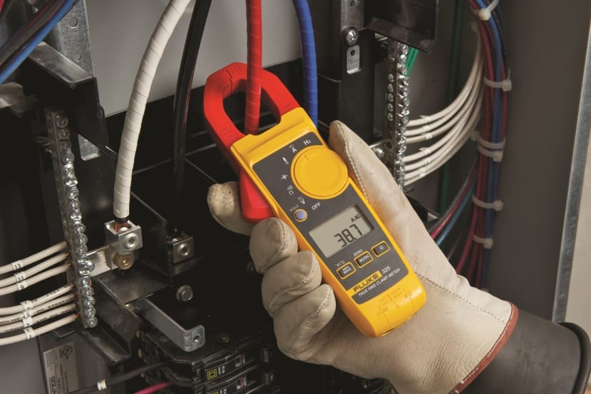
When the clamp's 'jaws' are placed around a conductor carrying ac current, the current is coupled through the jaws, which in turn is connected across the shunt of the meter's input, this is a similar process to that of an iron core in a power transformer passing current into a secondary winding. The current delivered to the meter's input (across the shunt) is a much smaller current and is a ratio of the number of secondary windings vs. the number of primary windings wrapped around the core. Normally the 'primary' is the conductor being measured (which the jaws are clamped around), so if the secondary has 1000 windings, then the secondary current is 1/1000 the current flowing in the conductor being measured. So, if 1 amp is being measured in the conductor, then this would result in 0.001 amps or 1 milliamp of current at the input of the meter.
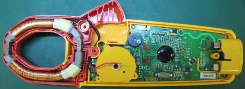
To measure ac and dc current, Hall Effect#1 clamp meters were developed that use rigid iron jaws to concentrate the magnetic field that encircles the conductor being measured, rather than having copper wires wrapped around the core as in a current transformer clamp.
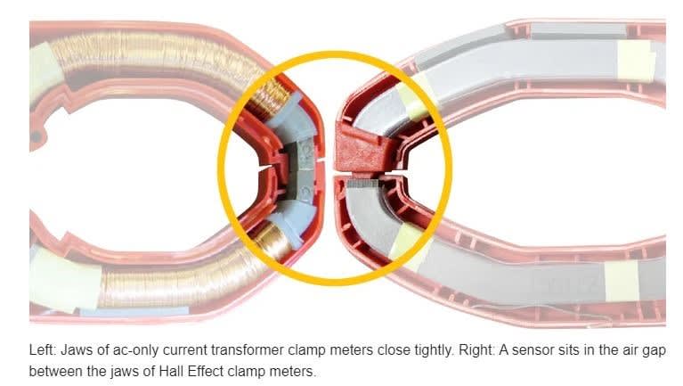
In the Hall Effect clamp, a gap exists where the jaw tips meet, which creates an air pocket that the magnetic field must jump, this gap is covered by a thin plastic moulding where a semiconductor known as a Hall Effect sensor sits (transducer that varies its output voltage when responding to magnetic fields). The output voltage from this sensor is then amplified and scaled to represent the current flowing through the conductor being measured.
Which Clamp Meter?
As already highlighted, in today’s advancing world, clamp meters are becoming more sophisticated, so when choosing a clamp meter you not only need to look at the specifications but also the features, functions, and the design of the meter, so that it will meet all of your measurement requirements, in fact choosing the right instrument for you may save money (may combine several instruments into one product (current, voltage, resistance, and continuity), but also save you space in your toolbox.
Other considerations that need to be taken into account are reliability and safety as these instruments measure very high current and voltages and you need confidence in the measurement being made and your safety taking the measurement. The meters are rigorously tested by Fluke to make sure they meet the latest safety standards and can withstand tough conditions as often these are thrown in tool cases or the backs of vans.
When choosing a clamp meter for yourself, it’s important to consider the following basic features to ensure you have the right meter for the job:
Resolution, Digits, and Counts
The meters resolution indicates how fine the measurement can be made (digits displayed), so knowing this you can determine how small a change can be seen in the measured signal. For example, a clamp meter with 0.01 amp resolution, indicates you can read changes down to 0.01 amp (or 10mA) of change as shown in the image below:
Accuracy
This is an indication of how close the meter’s displayed measurement is to the actual value of the signal being measured. The accuracy is generally quoted as a percentage of the reading. This means a meter displaying a value of 10 amps, with an accuracy of 1%, would mean the actual value could be anywhere between 9.9 amps and 10.1 amps
Also, the specification may also include a range of digits that are added to the basic accuracy (above example), this would then indicate how many counts the digit to the extreme right of the display may vary, so expanding the example above, the meter may have an accuracy of 1% + 2 digits, meaning the actual value could be between 9.7 amps and 10.3 amps
This may not sound a lot, but if you were measuring 600 amps, the true value could be between 592 amps and 608 amps!
Crest Factor
In today’s world, electronic power supplies are everywhere and cause the currents to become fairly distorted due to the harmonics they generate on the line, so the distribution system is no longer pure at 50 or 60 Hz sine waves. However electrical power system components such as fuses, conductors and thermal elements of circuit breakers are rated in rms current as their main limitations are heat dissipation, so for measurements to be made to check for overloading, you need to be able to measure accurately the True-rms value of the signal regardless of how distorted the signal may be.
Crest factor is a simple ratio of a signals peak value to its rms value and for a pure sign wave the crest factor would be 1:1.414, however if the signal has a very sharp pulse, then this would cause the ratio (crest factor) to be high.
Crest factor specification will only be found in meters that can measure True-rms measurements and it indicates how much distortion a signal can have and still measure within the meter’s accuracy specification. A crest factor of 2:1 or 3:1 should handle most electrical applications.
Measuring Current AC / DC
Current measurement, whether it be AC or DC is one of the most basic measurements an electrician can make with a clamp meter, with typical measurements being taken on various branch circuits of an electrical distribution system, to determine how much current is flowing through each branch circuit from the distribution system.
Typical fault finding can be on overheating circuit breakers or transformers, where the load measurement can be determined through current measurements on the branch, however as previously mentioned make sure you are using True-rms measurements otherwise if the current or voltage is non-sinusoidal you may get inaccurate readings.
Measuring Voltage
Voltage measurement is another common function of a clamp meter, as an engineer’s first job in troubleshooting a circuit is to check there is a proper supply voltage as if there is no voltage (or if it’s too high or too low), then this will cause the equipment connected to the circuit to fail, so the voltage problem should be corrected before investigating further.
A point to note with voltage measurements is that they can be affected by the frequency of the signal, typical clamp meters can measure ac voltages with frequencies from 50 to 500Hz, however, the bandwidth of a digital ac multimeter may be 100KHz or higher, so readings may be different between a clamp meter and digital multimeter. This is typically evident when measuring Variable Speed Drives (VSD) due to the harmonic content in the signal coming out of the VSD. A motor connected to a VSD only responds to the average value of the signal, and to measure that power, the input bandwidth of the meter must be narrower than its DMM counterpart. For testing and troubleshooting VSDs, Fluke has specifically designed the Fluke 375FC (905-5917) or Fluke 376FC (914-5424) Clamp Meters.
Resistance
A meter with resistance measurements can also help to troubleshoot and can be used to test the resistance of a contactor coil. Resistance measurements can be down to a few milliohm’s but up to billions of ohms (for insulators), however, measurements must be taken with the circuit power switched off, otherwise, the meter could be damaged (some meters provide protection in case of accidental contact with voltages, but this should be checked in the specifications).
Continuity
This can give a quick go/no-go to test for open and closed circuits and often features a buzzer for detecting closed circuits, so the user does not have to look at the display.
Special Functions
Other common measurement functions are:
- Frequency measurement – useful for tracing down harmonic problems in electrical distribution systems
- MIN / MAX Storage – a meter can be connected to the circuit and left to monitor the signal over a period of time, then the meter will store the highest and lowest measurements over that time period, so you can see if there are any fluctuations.
- In-rush current – handy for engineers who work with motors, as the meter will measure the maximum current drawn at start-up, which can give a good indication of its condition and loading.
Special Features
Functions that may make using your clamp meter easier include:
- Annunciators (display icons) – these show at a glance what is being measured (volts, ohms, etc)
- Data Hold - allows you to freeze the reading being displayed
- One-switch operation - select measurement functions easier
- Overload protection - prevents damage to the meter, circuit, and protects the user
- Auto-ranging - automatically selects the correct range, whereas manual ranging lets you lock into a specific range for repetitive measurements.
- Low battery indicator.
- Datalogging / Bluetooth – useful to be able to record readings over a long time and download them to a PC (often by Bluetooth) for incorporating into reports or records – an example of this is with Fluke Connect software.

Flexible Clamp Meters (Rogowski coils)
Sometimes it’s hard to position fixed clamps around a conductor (including in hard to reach places), so another type of current clamp is available called a Flex Current Clamp, or also known as Rogowski coils and sometimes air-cored coils:

Unlike current transformer and Hall Effect clamp meters, these types of clamps do not have an iron core, instead, they use a wound, helix-shaped coil which responds to the rate of change (known as the first derivative) of a conductor’s magnetic field around which they are placed. The faster the change in amplitude, then the more voltage generated by the coil. An integrator circuit in the measurement device converts that output to a signal that is proportional to the signal in the conductor.
An example of using this type of clamp can be seen in the video below:
Safety
Making safe measurements is critical, so you need to choose a meter suitable for the environment it will be used (a meter that meets the IEC category and voltage rating approved for that environment), for instance, if a voltage measurement needs to be made in an electrical panel with 480V, then a meter rated Category III – 600V should be used (This means the input circuity has been designed to withstand voltage transients commonly found in that environment).
When looking at the safety specified, be careful of the “Designed to meet specification….” As this does not mean the products have been independently tested, so always look for the standard tested too (IEC 1010), certification listing number, and approved by independent testing labs symbols such as UL, CSA, VDE, or TUV, to ensure the meter you choose is safe.
7 of the best Fluke Clamp Meters:
The following video illustrates 7 of the best clamp meters currently available from Fluke:
These products are all available from RS:
- Fluke 355 - RS (041-1970)
- Fluke 376 - RS (905-5914)
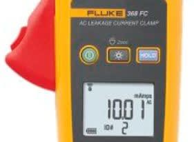
- Fluke 368 FC - RS (123-4544)
- Fluke 374 – RS (905-5911)
- Fluke 1630-2 FC – RS (134-7343)
- Fluke A3001 FC – RS (810-9142)
- Fluke A3004 FC – RS (881-2772)
Notes: #1 American physicist Edwin Hall (1855-1938) is credited for discovering the Hall Effect in 1879.