Taking your idea from concept to prototype - a stress ball demo: Part 2
Follow project
 Dave from DesignSpark
How do you feel about this article? Help us to provide better content for you.
Dave from DesignSpark
Thank you! Your feedback has been received.
Dave from DesignSpark
There was a problem submitting your feedback, please try again later.
Dave from DesignSpark
What do you think of this article?
 This article is the second part in the series of articles focusing on the Microchip's "Stress Ball" demo. We will look into the basic operation of USART peripheral and how to implement it with software examples.
Parts list
| Qty | Product | Part number | |
|---|---|---|---|
| 1 | Microchip AVR128DA48 Curiosity Nano Evaluation Kit GPIO Evaluation Board DM164151 | 204-2690 | |
| 1 | Microchip AC164162 for use with Mikrobus Click Modules, Xplained Pro Extension Boards | 193-6490 | |
| 1 | MikroElektronika MIKROE-1881, 4x4 RGB LED Matrix Display mikroBus Click Board | 136-0725 | |
| 1 | MikroElektronika Force Click mikroBus Click Board for Implement Force Pressure Measurement MIKROE-2065 | 136-0788 | |
| 1 | MikroElektronika RN4871 Click Bluetooth Development Kit MIKROE-2544 | 168-3003 | |
The Curiosity Nano development platform from Microchip is a small-sized, easily customizable rapid prototyping solution that provides developers with everything they might need to bring their project ideas to life. This article introduces the main features of the platform focusing specifically on a target microcontroller from AVR DA family. Together with our DesignSpark members, we will investigate one of the example codes from Microchip’s GitHub repository, while also discussing the basic operation of peripherals that were used in the demo, such as GPIOs, ADC and USART.
Peripheral Configuration - GPIO (Part 1)
Peripheral Configuration - USART
The Universal Serial Asynchronous Receiver Transmitter (USART) is one of the serial communication interfaces available in AVR® 8-bit microcontrollers. This section will walk you through the main features of USART peripheral, hardware components and registers as well as frame formatting.
The USART interface supports both synchronous and asynchronous modes of operation. The former means that there is a clock and data line, whereas asynchronous operation does not use a clock signal when data is being transferred. So how do we know if we are sending the right information through from one device to another?

USART Interface
To receive the data stream properly without the clock, the transceiver and receiver need to establish a common transmission rate between them, also called a baud rate, ahead of time. Only the two devices with the same baud rate can communicate. We will discuss how to initialize the baud rate in the code implementation section.
USART frame format
The USART data transfer is based on data frames, as shown in the diagram below. In the IDLE state, the voltage level is HIGH and there is no transmission. The transmission starts with the Start bit (St) at the LOW state. It is then followed by from 5 up to 9 data bits (n). The Parity (P) bit is used for error detection and can either be even or odd. The parity check is optional, as indicated by square brackets. Similarly, the Stop (Sp) bit can either be 1 or 2 bits, but it will always be transmitted as HIGH logic. The next transmission can start immediately (St) or remain idle (IDLE).

USART Frame format
Let’s consider an example of the USART data frame. The data bits are 8-bit long, and we want to send an even parity bit and a single stop bit. As the timing diagram demonstrates, we start of with IDLE state before sending a digital low signal to represent the start of the data frame. Each individual bit has a certain duration dictated by the baud rate of the USART peripheral. The data bits are sent from the least significant bit to the most significant bit. If the parity check is set to even parity, parity bit (P) in our example will be 0 since the input data frame has even number of 1s. However, in case of odd parity, P bit would have been 1 for the given data input. We then finish off with a single stop bit (Sp) before going back to the IDLE state or starting off the communication all over again.

USART Frame Example
USART Block Diagram
Without going into too much detail about the internal structure of the USART peripheral, consider the block diagram below. There are two pins for transmitting (TXD) and receiving (RXD) the data signal. If synchronous mode is selected, the clock is fed through the pin XCK. The last pin, XDIR, is used when we want to use the USART peripheral to implement RS-485 communication protocol (refer to page 386 of the device datasheet for more information on how RS-485 is implemented).

USART Block diagram
The transmitter consists of a two-level write buffer and a Shift register. The data to be transmitted first arrives at the TXDATA register, buffered at the TX Buffer and TXDATA, then passed to the TX Shift Register, according to the frame format that has been set by the control logic. Likewise, the serial data arrives at RXD and passes to the RX Buffer receive buffer through the RX Shift Register and then stored at the RXDATA register.
USART Configuration
Before we dive into how to configure the USART peripheral, let’s have a look at the register structure first. There is a lot going on, but I highlighted the registers I would like to focus on in this tutorial in orange. Try to understand them first before advancing further, but feel free to refer to the datasheet for more details.
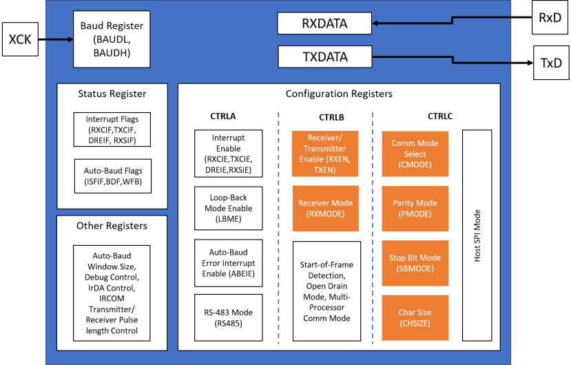
USART Register Summary
We already discussed that the data bits received at the RXD pin are saved at the RXDATA register. From our data frame discussion, you might also remember that sometimes the data signal might take 9 bits, which is 1 bit more than a single 8-bit register can hold. Therefore, RXDATA consists of two 8-bit registers to capture LS and MS bits as well as other some other bits to reflect status of the received data. The same principle applies to the TXDATA register, where DATA[0:7] and DATA[8] bits are saved in the TXDATAL and TXDATAH sections respectively.

RXDATA and TXDATA Registers
The configuration process involves setting up parameters such as pin mode, baud rate, mode of operation, character size, stop and parity bits.
Setting TXD and RXD pins
The first step would be to decide which pins we will be using for USART transmission. Referring back to the pinout diagram for AVR128DA48 Curiosity board, there three ports that support USART pins: USART0 (PORT A), USART1 (PORT C) and USART2 (PORT F). For each RXD and TXD within these ports, we need to change the state of DIR register to set them either as input or output.
Baud Rate
The BAUDL and BAUDH register pair holds 16-bit value for the baud rate information. The baud rate is given in bits per second (bps) with typical values selected as 4800, 9600, 19200, 38400, 57600, 76800, 115200 etc. To convert the baud rate in bps to the BAUD register value, the following equations are given in Table 25-1 of the device datasheet:

Equations for setting baud rate value in the BAUD register
Here, S stands for the number of samples per bit and it is equal to 16 for asynchronous (normal speed) mode.
Mode of Operation
There are several operation modes available with the AVR® DA family microcontrollers. We have only looked at asynchronous and synchronous modes, which can be set by accessing CMODE[1:0] bit fields within CTRLC register.

Frame Format
The CHSIZE[2:0] bit field of CTRLC register can be configured to select how many bits are allocated per character within the data frame.

Parity Mode
The parity check mode can be enabled or disabled within the PMODE[1:0] bit field of CTRLC register. When enabled, the receiver calculates the parity of the data bits in incoming data frames and checks the result with the Parity bit of the corresponding frame.

Stop Bit Mode
The stop bits are set within the SBMODE bit field with binary values 0 and 1 for a 1 or 2 stop bits, respectively.

In the code examples below, you will see how these parameters are set using bitwise operations.

Register Summary Table
Code implementation – Sending “Hello World” to a PC
Let’s start off with a simple example USART implementation that can be found in the Microchip’s GitHub repository. The “Hello World!” is sent through TXd (PC0) pin every one second to the terminal on a PC. The baud rate is set to the 9600 bps.
The data format is selected to be 8-bit long, which corresponds to the value 0x03 to be passed to the CHSIZE [2:0] bit fields. The USART_CHSIZE0_bm and USART_CHSIZE1_bm bit masks toggle the bit at positions 0 and 1 of CTRLC register, respectively. Lastly, the corresponding output pin is enabled for transmission by writing 1 to the TXEN bit field of CTRLB register.
USART initialization
void USART1_init(void)
{
    PORTC.DIRSET = PIN0_bm;                             /* set pin 0 of PORT C (TXd) as output*/
    PORTC.DIRCLR = PIN1_bm;                             /* set pin 1 of PORT C (RXd) as input*/

    USART1.BAUD = (uint16_t)(USART1_BAUD_RATE(9600));   /* set the baud rate*/

    USART1.CTRLC = USART_CHSIZE0_bm
                 | USART_CHSIZE1_bm;                    /* set the data format to 8-bit*/

    USART1.CTRLB |= USART_TXEN_bm;                      /* enable transmitter*/
}
The following code snippet implements a function for transmitting a single character through the USART interface. Before writing a character to the TXDATA register, we need to ensure that the previous transmission is completed by checking the STATUS register. To do that, we need to wait until the DREIF (Data Register Empty Interrupt Flag) flag is reset to 0 which signifies that the TXDATA register is empty.
Sending a single character
void USART1_sendChar(char c)
{
    while(!(USART1.STATUS & USART_DREIF_bm))
    {
        ;
    }

    USART1.TXDATAL = c;
}
Once the function for a single character has been defined, we can loop through individual characters to send a complete string.
Sending a string
void USART1_sendString(char *str)
{
    for(size_t i = 0; i < strlen(str); i++)
    {
        USART1_sendChar(str[i]);
    }
}
Code implementation – Sending ADC result to PC and BLE module
Going back to our demo, the USART interface is used to transmit ADC result to the PC terminal as well as to the BLE module. You will notice that the code implementation is very similar to the example code we considered above.
Initializing USART0 & USART1
/********************************************************************usart_ble_init**************************************************************************************
Initializes USAR0
BLE communication. PA0 TX, PA1 RX
Baud Rate : 115200
***************************************************************************************************************************************************************/
void usart_ble_init()
{
	USART_BLE_PORT.CTRLA =  USART_RXCIE_bm;
	USART_BLE_PORT.CTRLB = USART_TXEN_bm |  USART_RXEN_bm ;
	USART_BLE_PORT.BAUD = (F_CPU * 64.0) / (BAUD_RATE * 16.0);
}
/********************************************************************usart_cdc_init**************************************************************************************
Initializes USART1
CDC Virtual come port is connected to USART1 on AVR128DA48 Curiosity Nano board, PC0:TX,PC1:RX
Baud Rate : 115200
********************************************************************************************************************************************************/
void usart_cdc_init()
{
	USART_CDC_PORT.CTRLB = USART_TXEN_bm |  USART_RXEN_bm ;
	USART_CDC_PORT.BAUD = (F_CPU * 64.0) / (BAUD_RATE * 16.0);
}
When receiving the data from BLE module, we need to make sure that there is no unread data in the RXDATA register by checking the RXCIF flag of the STATUS register.
Send and receive functions
/********************************************************************usart_put_c**************************************************************************************
Transmit data through USART
***************************************************************************************************************************************************************/
void usart_ble_put_c(uint8_t c)
{
	while (!(USART_BLE_PORT.STATUS & USART_DREIF_bm));
	USART_BLE_PORT.TXDATAL = c;
}

void usart_cdc_put_c(uint8_t c)
{
	while (!(USART_CDC_PORT.STATUS & USART_DREIF_bm));
	USART_CDC_PORT.TXDATAL = c;
}

uint8_t usart_ble_get_c()
{
	while (!(USART_BLE_PORT.STATUS & USART_RXCIF_bm))
	;
	return USART_BLE_PORT.RXDATAL;
}

uint8_t usart_cdc_get_c()
{
	while (!(USART_CDC_PORT.STATUS & USART_RXCIF_bm))
	;
	return USART_CDC_PORT.RXDATAL;
}
These building blocks are then used in the main.c to implement transmit_to_BLE and transmit_to_terminal functionalities.
Peripheral Configuration - ADC (Part 3)
Resources
Rapid Prototyping with the Curiosity Nano Platform – Microchip University
AVR1000b: Getting Started with Writing C-Code for AVR® - TB3262
How to Use Force Sensitive Resistor with 12-bit ADC - AN3408
AVR® DA Family Datasheet - Microchip