Taas Energy's Equate Windfarm Proposal
Follow article
 Dave from DesignSpark
How do you feel about this article? Help us to provide better content for you.
Dave from DesignSpark
Thank you! Your feedback has been received.
Dave from DesignSpark
There was a problem submitting your feedback, please try again later.
Dave from DesignSpark
What do you think of this article?
Introduction
This project was designed to reflect how groups of engineers work together in industry to design a wind farm. The UK is one of the best locations for wind power in the world! All of us involved hoped to have exposure to the power generation industry. We came up with our company name TAAS energy. We had to investigate the location of the turbine selection, social and environmental impacts, as well as the financial aspects of project management.
Team Organization
We split our group into two groups of two: Team 1 obtained their licences to use WAsP wind modelling software to investigate the wind speeds at the different locations offered at the three possible heights (85, 95, 110m) while Team 2 looked at MagicMaps and SNH's Nature Scot map to take note of geographic features that would affect the windfarm's performance. The following Gantt Chart was used to allocate roles, facilitate planning and set deadlines:

Figure 1.Distribution of tasks in TAAS Energy team
Site Selection & Analysis
Using MagicMaps and the Nature Scot map, geographic features were noted and compared between the sites. The final location was selected using the weighted properties selection method, as is shown in the table below:
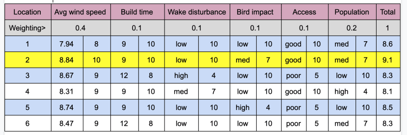
Having settled on Location 2, further analysis was required using various mapping software to highlight area restrictions and points of importance. Most vitally, the selected site is on the periphery of Clyde Muirshiel Regional Park, hence extensive measures would have to be put into place to mitigate environmental impacts by consulting local authorities and experts. A grid connection exists close to the proposed site which would reduce transmission line connection costs, while the presence of a farm to the east and housing to the south of the site creates the need for a noise and shadow flicker exclusion zone. Restricting the farm size to eight turbines and their size to 85m in height for 100m in diameter would result in an exclusion zone of only 750m. A diagram of the site is shown below.

Technical Design
Knowing that the windfarm is to be built in Inverclyde after comparing the six different proposed sites considering access, building time, wind speed, presence of protected species etc. There are three hub height options for wind turbines. The WAsP software was used to analyse wind velocity change in each location. It is seen in the velocity comparison at three different hub heights in figures 2,3 and 4. The power generation changes depending on wind speed. The power curve of 1st turbine type is seen in figure 1. The efficiency is about 28% for all turbines. It is decided to select an 85m hub height for design.
|
Turbine |
Power Rating(MW) |
Hub Height (m) |
Rotor Diameter (m) |
Cost per Turbine |
|
1 |
2,5 |
85 |
100 |
£1290000 |
|
2 |
3,6 |
95 |
120 |
£2322000 |
|
3 |
5,6 |
110 |
150 |
£4334400 |
Table 1.Turbine types and characteristics
|
Hub Height (m) |
Power Generation (MW) |
Max power |
Efficiency |
|
85 |
2,125 |
2,5 |
0,85 |
|
95 |
3,094 |
3,6 |
0,859 |
|
110 |
4,781 |
5,6 |
0,853 |
Table 2.Comparison of turbines depending on average wind speed


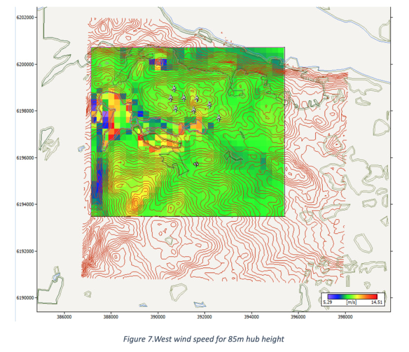
The velocity difference is around 0.8 m/s between the minimum and maximum hub heights for the lowest average (for all directions) wind velocity. Therefore, 85 meters is thought for the optimum design conditions, which also reduces costs dramatically. In addition, the prevailing wind direction at location 2 is given as west/southwest. The mean velocity of both directions was compared in figures 6 and 7. It is seen that the wind velocity reaches around 10 m/s in these directions. Especially in the west direction, the wind speed is higher than southwest direction. For this reason, the direction of wind turbines is chosen as west to benefit wind power efficiently.
|
Site |
Location [m] |
H [m] |
A [m/s] |
k |
U [m/s] |
E [W/m²] |
RIX [%] |
dRIX [%] |
|
WTG1 |
(392623,1, 6197563,0) |
85,0 |
9,8 |
2,04 |
8,67 |
737 |
3,6 |
0,2 |
|
WTG2 |
(391555,8, 6197898,0) |
85,0 |
9,3 |
2,01 |
8,28 |
653 |
6,4 |
3,0 |
|
WTG3 |
(390781,5, 6197961,0) |
85,0 |
10,0 |
2,00 |
8,82 |
790 |
9,6 |
6,2 |
|
WTG4 |
(390572,2, 6198421,0) |
85,0 |
10,1 |
2,02 |
8,92 |
807 |
7,8 |
4,4 |
|
WTG5 |
(391681,4, 6198400,0) |
85,0 |
11,1 |
1,97 |
9,86 |
1110 |
5,0 |
1,6 |
|
WTG6 |
(392225,5, 6198128,0) |
85,0 |
10,4 |
2,01 |
9,19 |
889 |
3,9 |
0,5 |
|
WTG7 |
(391137,3, 6198421,0) |
85,0 |
10,1 |
1,97 |
8,96 |
838 |
6,1 |
2,7 |
|
WTG8 |
(390718,8, 6198819,0) |
85,0 |
10,8 |
1,95 |
9,58 |
1033 |
6,3 |
2,9 |
Table 3.Site wind climates

|
Parameter |
Total |
Average |
Minimum |
Maximum |
|
Net AEP [GWh] |
91,070 |
11,384 |
10,248 |
12,356 |
|
Gross AEP [GWh] |
93,923 |
11,740 |
10,644 |
12,792 |
|
Wake loss [%] |
3,04 |
- |
- |
- |
Table 4.Gross AEP: Annual energy production for a turbine without other turbines’ effect, Net AEP: Waked energy production with regarding other turbines’ effects
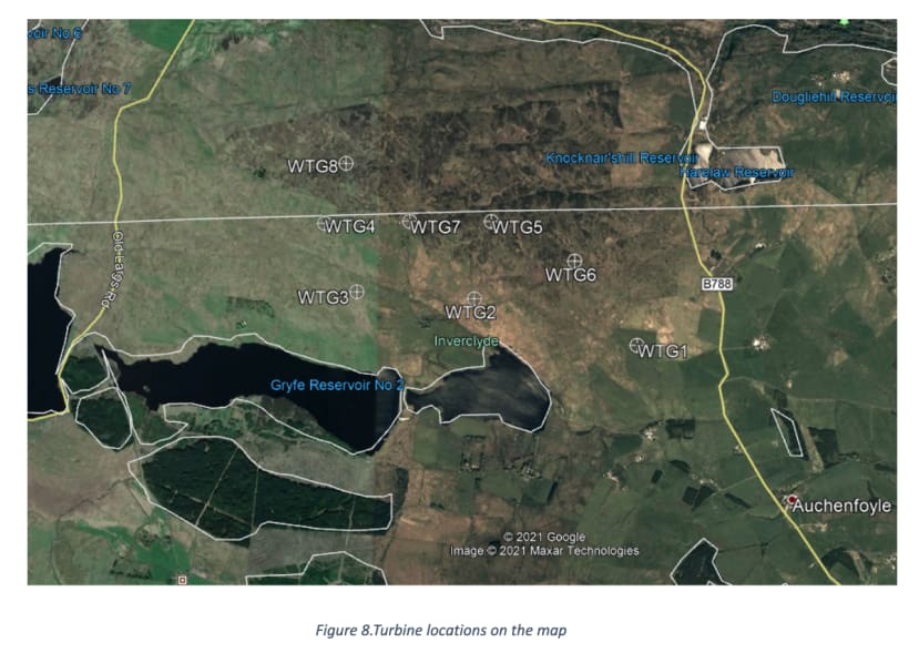
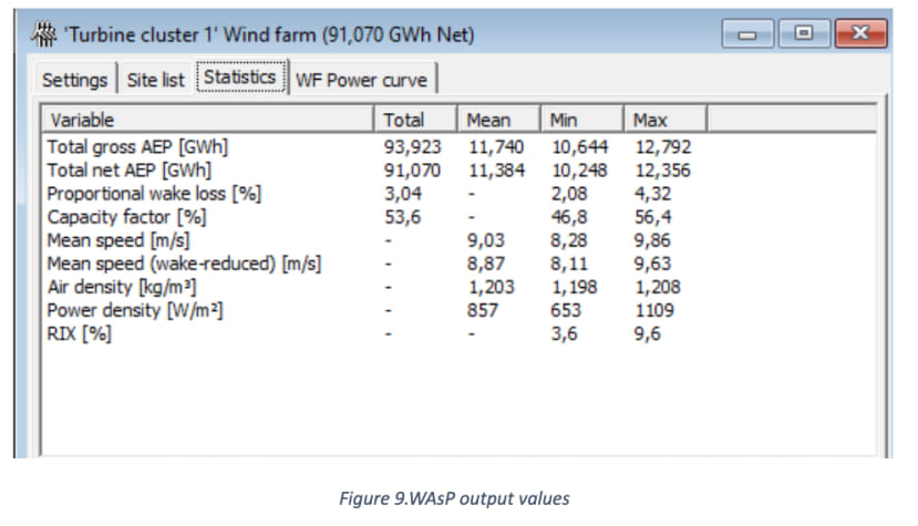
It is seen energy production of a turbine with and without other turbines’ effects in table 2. The wake loss can be seen around 10-20% depending on the locations of each turbine (Archer et al., 2018). The wake loss is the difference between these values and it is around 3% which is acceptable in this study. The turbines are located depending on regulations to avoid noise effect and shadow flicker in figure 7. In addition, the maximum RIX value which is desired to below 10% is found as 9.6% for the maximum value which is seen in figure 8. The exact turbine locations are given in table 4.
|
UTM WGS84 coordinates |
Geographic Coordinates |
|
|
WTG1 |
392623.1, 6197563.0 |
55.911499, -4.717844 |
|
WTG2 |
391555.8, 6197898.0 |
55.914268, -4.735044 |
|
WTG3 |
390781.5, 6197961.0 |
55.914659, -4.747452 |
|
WTG4 |
390572.2, 6198421.0 |
55.918743, -4.750985 |
|
WTG5 |
391681.4, 6198400.0 |
55.918805, -4.733237 |
|
WTG6 |
392225.5, 6198128.0 |
55.916484, -4.724427 |
|
WTG7 |
391137.3, 6198421.0 |
55.918871, -4.741947 |
|
WTG8 |
390718.8, 6198819.0 |
55.92235, -4.748801 |
Table 5.Coordinate conversion for turbine locations
Environmental Impact
The proposed wind farm lies within the periphery of Clyde Muirshiel Regional Park, which covers anarea of 280 square kilometres Inverclyde, North Ayrshire and Renfrewshire. Several wind farms exist within its boundaries, notably along the west coast due to strong southwestern winds.
If placed in the vicinity of birds nesting or other protected sites, wind turbines pose a real threat due to the risk of collisions with wildlife, as well as noise disturbance during construction and operation. To reduce these risks, turbines should be erected far from major migration pathways and important habitats, which would be the case concerning the proposed site which is a suitable 3km distance from a Natura 2000 protected site to the south. Still, compensation efforts may be required, so a full EIAwould have to be carried out over several years.
Generating energy from the wind does not release any carbon emissions, however, one must be wary of problems posed by wind turbine decommissioning. The costs of this must be taken into account, while the technology exists where epoxy and fibre can be split to be recycled.
Social impacts
Not only is the area populated, but the presence of the Regional Park is sure to stir up local emotion which could turn against the project. Actions must therefore be taken to minimise the impact on the local surroundings, such as these:
- The size of the turbines and of the wind farm as a whole is kept to a minimum to lessen the potential impact on the local surroundings.
- Shadow flicker: the flickering effect caused when rotating wind turbine blades periodically cast shadows over neighbouring properties as they turn, through constrained openings such as windows. A shadow exclusion zone of 500m must be ensured.
- Noise:Wind turbines are relatively quiet and are designed to operate within 5 dB of noise levels at nearby areas, but the noise created is constant and high-pitched due to the noise of the generator and gears in the nacelle. A noise exclusion zone of 750m must be ensured.
- Wind turbines are created to withstand high winds and when wind speeds increase beyond the design speed, or when ice forms on the blades it can withstand this. In extremely rare cases, high winds can cause structural failure of the turbine tower resulting in the tower toppling. Fences, sheep barns and roman ruins all exist within the proposed site area, all of which must be kept outside of the area affected by a potential topple.
- A community support scheme financed by a Community Development Fundto address local needs brought forward by local authorities, improve access roads, and provide the necessary environmental compensations required to mitigate the farm's impact on local habitats.
- Commitment to hiring local for contract work for the wind farm empowers the local community, with required training being financed by the aforementioned community support scheme.
The group has interacted with residents, we have taken the concerns of the residents in the area and their needs, and have an engagement plan with the community and other key stakeholders.
Financial plan
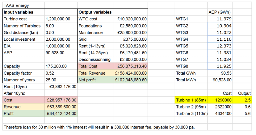
The source of costs of the proposed windfarm can be divided into four sections:
1) Initial cost of the turbines, access roads, foundations and grid connection spread over the nine months of construction
2) Operating cost of maintaining the turbines and rent for the land occupied
3) Decommissioning of the turbines, the cost of which has been estimated based on data from ARUP (commissioned by the UK gov in 2018)
4) EIA and compensating schemes (allocated budget of£1 million) and Local Development Fund (allocated budget of£2 million)
Meanwhile, the farm will be generating revenue at£70/MWh, hence the net profit can be calculated. Funding has already been secured with a loan for£30 million with 1% interest over a 25-year span.
Conclusion
In conclusion, we have managed to investigate the location, turbine selection, social and environmental impacts. Also the financial aspects of project management. As a team, we have worked together to consider any potential issues regarding our wind turbine.
References
Archer, C. L., Vasel-Be-Hagh, A., Yan, C., Wu, S., Pan, Y., Brodie, J. F., & Maguire, A. E. (2018). Review and evaluation of wake loss models for wind energy applications. Applied Energy, 226(September 2020), 1187–1207. https://doi.org/10.1016/j.apenergy.2018.05.085