Robotic Lawn Aerator - Part 1 | Lawn Aerator Design | DesignSpark
Follow article Dave from DesignSpark
How do you feel about this article? Help us to provide better content for you.
Dave from DesignSpark
Thank you! Your feedback has been received.
Dave from DesignSpark
There was a problem submitting your feedback, please try again later.
Dave from DesignSpark
What do you think of this article?

Introduction
Robotic Lawn Aerator is a fourth year Group Design Project from the University of Southampton with a goal to design, build and test an autonomous lawn aerator (machine to insert holes in lawns). The project was started last year by another group, but unfortunately was interrupted by the COVID-19 pandemic. We, as a team of six master’s mechanical engineering students specialised in multiple areas such as computational, acoustical and mechatronics, are tasked to revisit the existing design, build it and assess its performance.
Lawn Aeration
Lawns are the carpets of our gardens and with our constant trampling and abuse, they can degrade significantly without proper care. One of the most important tasks is to introduce holes into the compacted soil to enable nutrients and oxygen to reach the roots or also known as aeration.
Traditionally, aeration is done by the mechanism called ‘coring’ which involves displacing soil by forcefully punching or inserting tubes into the ground to create holes. This method requires a significant downward force to displace the soil and in the case of a conventional aerator, the force is generated by the weight of the machine. This mechanism cannot be imported into a robotic lawn aerator. As we want an aerator that can operate on its own without external forces contributing to the process and given our budget, it would not be feasible to design something of that scale.
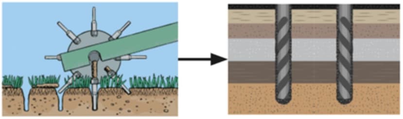
With this in mind, we investigated several alternatives. One idea came from the fact that we know oil and gas companies have for years used drills to burrow the ground for oil. We believe that the same theory used in fracking can be translated into lawn aeration as well. Drilling method stands out from our list of options as it significantly reduces the force needed to displace the soil and the efficiency of the machine can be scaled up by using multiple drills.
Drill mechanism
Design
To reiterate, by aiming to have a lightweight prototype we eliminated the option of a single spike roller, which provides force into the ground by means of its weight, instead opting for drills, which could then be driven into the ground. From research, it became apparent that auger drill bits would be the most suitable, since they are self driving and would require less force to be pushed into the ground.
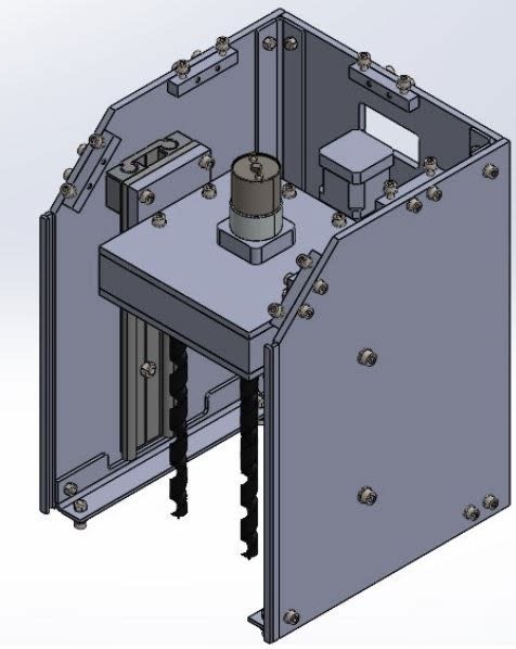
As a baseline we set ourselves the challenge of turning 4 drill bits at the same time, to provide a realistic aim for a prototype and to design it in such a way that a repeating pattern could easily expand the robot if it were to be built up in the future. To solve the issue, we used five spur gears provided by RS 4x (878-7929) and 1x (878-7926) in a 1.5 : 1 ratio, speeding up the gear attached to the drill shaft and allowing us to use a lower rpm motor. However, a larger ratio would allow us to use an even slower motor but would begin to go unstable.
In order for the drill to enter the ground, the team is using a linear actuator as the driving force with 2 linear rails, provided by igus, to spread the load of the gear housing as it moves up and down. Key challenges for this aspect will be to minimise the effects of forces in different directions to the motion, for example, if there is a large torsional force experienced by the side panels. This could cause the rails to misalign, stopping any vertical motion altogether.
Electronics
The main component of the Drill mechanism is the DC motor that drives the central gear. To decide on the motor to be used, calculations on the minimum rpm and the maximum torque of the DC motor were made based on drill dimensions and the properties of topsoil, either found directly or approximated based on properties of other soil types.
The linear actuator had been inherited from last year’s team and was deemed to be fit for purpose after carrying out research of its specification and the loads it would take on from the weight of the gear housing mechanism. The final parameter of importance was the length it would drive over. We decided that 150 mm was large enough to accommodate the length of the drill bit and give enough clearance over the ground that the aerator can overcome obstacles that would be found on a lawn.
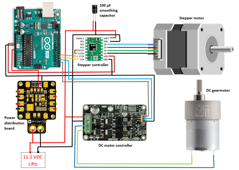
Having chosen the relevant actuators for the mechanism, the entire electronics of the Drill can be established. Both the stepper motor of the linear actuator and the DC gear motor that drives the drills require driver boards to control their speeds and directions. The drivers are subsequently controlled by the brain of the mechanism, the Arduino microcontroller (715-4081) .
To power the components, we need a source and thanks to its small size, weight and portability, a three-cell Lithium-Polymer (3S LiPo) battery is chosen to supply power to the entire Drill. Each cell of a LiPo battery has the nominal voltage of 3.7 V and therefore a 3S battery can provide 11.1 V. This voltage directly powers both the stepper motor inside the linear actuator and the DC motor that drives the drills. However, the Arduino Uno cannot handle that high of a voltage and therefore a power distribution board is needed to step the voltage down to a more manageable value for the Arduino of 5 V. The full wiring scheme can be seen in the image below.
Propulsion system
The Cube
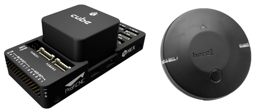
Our group is given a head start since we are able to retrieve the expensive GPS system from the last year group. The brain is a piece of electronics called the Cube, a further iteration of the Pixhawk (2.1), which essentially is an autopilot that drives the robot automatically with its wide range of onboard sensors in the likes of compass, accelerometer, barometer etc. Accompanying the Cube is the Here2 GNSS module that provides GPS positioning up to 2.5 m of accuracy.
There are various firmware (the code that runs on the electronics) that can be used by the Cube but we have chosen ArduPilot Rover thanks to its simplicity as this is the first time we work with a Pixhawk, a flight controller that is often used for drone applications instead. However, ArduPilot is still not “human-readable” so a ground control station (GCS) software is needed to bridge the gap. Again for ease of use reasons, we opted for an application called Mission Planner as our primary method of programming the Cube.
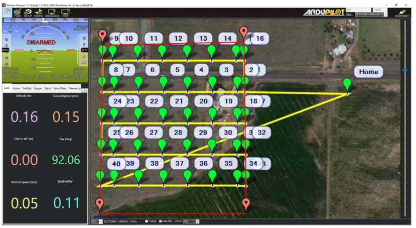
The connection between the Cube and the computer running MissionPlanner software can be accomplished by either a physical cable or wirelessly via radio telemetry (sharing of information). Once established, data such as altitude, ground speed, yaw angles, etc., can be monitored in real-time on the GCS screen as shown on the left below. More importantly, however, the GCS is capable of assigning waypoint (longitude and latitude coordinates) missions which are carried out later by the autopilot automatically. As seen in the right side of the figure below, a gardener can, for example, assign a certain aeration path on a screen for the robot to follow after a click of the upload button.
Drive system
We have opted for a 4-wheel drive (4WD) system since this configuration yields the highest stability and torque generated since each wheel is driven by a separate motor. However, the motors on each side are connected together as one unit so that the robot can turn when the speed on one side is different from the other. During steering, the wheels need to skid or slip on the ground as they are mounted fixed and this is known as skid steering.
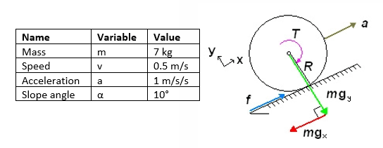
The workhorses in a drivetrain are the motors and to choose the correct ones for the task, the torque and speed needed by each motor is required. We consider worst-case scenarios, for example, calculating torque through modelling motors accelerating up an incline using overestimates of parameters we do not know having not produced the robot yet such as mass or slope of lawns (some data and the force diagram is shown in the figure as one example). In addition, we account for the discrepancies resulting from making assumptions such as perfect efficiency and negligible internal resistances by applying a safety factor of 2 to all specifications. Doing this, we know if the components can work in those situations, they can work in less demanding cases.
Schematic
The entire schematic of the propulsion system is shown in the figure below. At the top, wheels and motors are connected to the motor controller with the left and right sides lumped into their own units for skid steering. In the bottom right-hand side are the connections of all components that plug into the Cube to provide GPS, telemetry and radio control. The drivetrain and the autopilot are linked together by wiring the control signals from the Cube directly to the underside of the motor controller.

The power distribution of the propulsion system starts with the source being the 3S LiPo battery shown in the bottom left-hand side. The 11.1 V from the battery first goes to a buck converter to step down the voltage to 5 V which is used to power the Cube and its peripherals. Aside from the buck converter, the power adapter unit on the left-hand side also provides voltage monitoring capability to the Cube which is extremely important as LiPo batteries should never go below a 3.0 V/cell. The power adapter also lets the full 11.1 V of the battery to pass through and this is connected straight to the battery terminals of the motor controller, next to the motor connections at the top. The controller board modifies how much and the polarity of this voltage is received by the motors to control speeds and directions.
Testing progress
We are very fortunate to receive the Cube at the very start of the project because unlike the Drill mechanism where detailed 3D modelling can be done, the compatibility of Propulsion electronics needs to be validated practically before building anything on top. Priority is given in our first purchase order to consist of mainly Propulsion components. With a simple laser cut plywood platform, we are able to mount the motors, connect electronics according to the wiring scheme presented above and create our first-ever prototype robot as seen in the left image below.
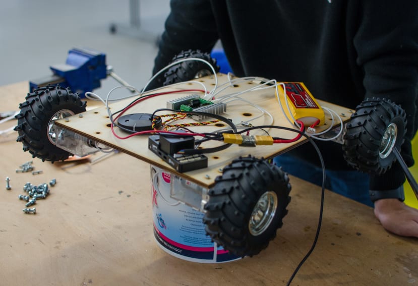
Initial testing yields positive results where all components are working independently and as a system, the motors are successfully driven with a signal from the GCS to the Cube which is then translated to tell the motor controller to impose a voltage between the motor terminals (see video). We are very happy with the outcome at the current stage because it paves the way for more GPS testing after Christmas term break.
Chassis
Design
The base and chassis were modelled as a separate subsystem which builds upon the base seen above for the electronic testing. For prototyping and testing reasons, we opted for a temporary laser cut plywood piece. Having a blank canvas allows gauging the space needed for wiring, electronics, and the drill mechanism. It also allows us to explore potentially wasted space, and alternate mounting positions.
For the working prototype, design decisions must be made in conjunction with the drill mechanism. Coupling the two subsystems, lead to torsional and static loads due to the weight of the drill mechanism, which was informed from simulated FEA tests. To improve structural rigidity and to accommodate the other design requirements listed, future iterations are to have the following features. Metal framing along the base plate to improve structural rigidity upon mounting the drill mechanism; switching out the plywood base for a weatherproof option such as Perspex, acrylic or plexiglass; adding the mounting holes for the drill mechanism; and if required framing to mount the outer casing of the prototype.
FEA
Finite element analysis is used to find areas of high-stress concentrations and potential points of failure that might occur due to our design choices. This analysis is important as it would ensure the model does not fail under the predicted workload, thus potentially minimizing the cost of production. Our FEA team has formulated different scenarios that reflect real-life situations.
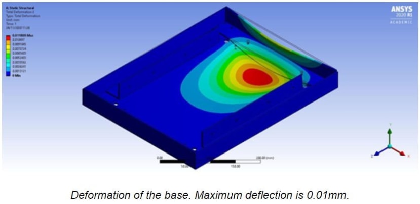
According to the weight of each component of the prototype, the weight is estimated to be around 10.52kg. With this, we can apply the mass according to the calculated centre of gravity.

Simulating with the weight of the prototype on the base, the deflection and stress experienced by the mass is minimal and is significantly below the yield stress.
Torsional rigidity is important as it affects its dynamic characteristics such as handling and rollover. In this analysis, loads are applied with equal magnitudes but opposite directions at the front of the base while fixing the rear end where the wheels are. Using this loading condition will create a case of pure torsion.

Results from FEA indicate that maximum stress occurs at the corners of the base when a torsional load is applied. Although the maximum stress simulated does not cause major concerns, design changes could be made by reinforcing the corners to improve the overall rigidity.
Translational vibration presents itself as a complication within the design, stemming from the several rotational components (motors and gears) within the build. The chassis and base are required to be rigid whilst operating to ensure the electronics mounted on them will not be damaged. These vibrations present as problems when their excitation frequency coincides with the fundamental frequencies of the chassis and base, which may lead to rattling and resonance.
Having identified the vibrational sources, calculations were made to determine the frequencies excited by the gear and motors, which were found to be 8.97 Hz and 13.45 Hz which were derived from the RPM of the motors. The structure was then simulated under free vibration conditions to determine their fundamental frequencies. For the current working design, it is found that the fundamental frequencies are much higher than that of the excitation frequencies. This is desirable as it suggests the structure is structurally rigid during operation.
Next steps
Drill
The next stage of development for the drill mechanism is to build and assemble the first iteration, ready for testing. The structure has been designed to be laser cut, meaning a shorter lead time because it can be manufactured ourselves quickly and easily. Parts we are not manufacturing have mostly been provided by either RS or igus, including the gears, linear rails and bearings.
Once assembled, the electronics can be attached and programmed ready for testing. One of the key principles of the design is that the final product can be split into 2 sub-systems, being the drill mechanism and the chassis.
Propulsion
Regarding the propulsion system, we now have the first prototype with all working electronics. The keen reader amongst us might spot the inclusion of radio control (RC) in the propulsion schematic and the next milestone is to incorporate this to have a remote control to drive the prototype around. The ultimate goal is to have a robot that navigates using GPS and initial testing of this feature is expected to be sporadic given the members’ limited experience in the area. Therefore, having some manual takeover capability with RC acts as a safety net for when things go wrong. In short, in the next article, we will explore the integration of radio control to the prototype as well as test GPS functionalities such as waypoints following and basic mission executions before merging Propulsion with the Drill mechanism.
Chassis
The current design is without a casing, which serves as a housing for the subsystems (chassis and drill mechanism), for weatherproofing and aesthetics. The next step is to design a casing to follow the following criteria. The casing should not add substantial weight to the current prototype and its effect on the overall structural rigidity of the product should be minimal. It should also serve the purpose of protecting the electrical and mechanical components housed within from rain, dirt, and snow. The casing will also need to be easily removable such that the components within can be assessed easily.
In Part 2, we will work towards a complete prototype where the two subsystems must be coupled, which would mean the aeration and propulsion system would be merged. This would lead to torsional forces and reaction forces on the system. To predict and accommodate for this, the team aims to complete a set of FEA tests prior to manufacture. These tests will be aimed at identifying and reducing the effects of the torque balance on the gears and linear actuators as well as the static loads on the motor bearings. The material choices of the system are also set to be reviewed and simulated to inform the best possible design solution.
Part 3 sees the team decided to focus on the development of the drilling system, where the team successfully carried out aeration test on different soils along with the rock detection system using current monitoring