Robot navigation with Sonar
Follow article
 Dave from DesignSpark
How do you feel about this article? Help us to provide better content for you.
Dave from DesignSpark
Thank you! Your feedback has been received.
Dave from DesignSpark
There was a problem submitting your feedback, please try again later.
Dave from DesignSpark
What do you think of this article?

The scanning sonar head on top of a M.A.R.S. rover. Great for navigating around a room on Earth; Lidar operating using the same principles would probably be a better bet on Mars.
What is Sonar?
Sonar is a method of finding the distance to an object by measuring the time it takes for a pulse of sound (usually ultrasound) to make the round trip back to the transmitter after bouncing off the object. At sea level, in air, sound travels at about 344 metres per second (1130 feet per second). In practical terms this means 2.5cm is covered in about 74 microseconds. These sorts of numbers are easily managed by a simple microcontroller system. Imagine the time measurements you would have to make if light was used instead! In principle, all you do is send a burst of ultrasound from a suitable transmitter, setting a clock or timer running at the same time. When the receiver picks up the reflected signal or ‘echo’, the clock is stopped and the elapsed time is proportional to the distance. Easy. Well, yes and no. There are some practical problems that need to be addressed.
Polar Plotting
Just like a radio frequency antenna, an ultrasonic transducer can be designed to emit a beam of energy with a particular shape. In fact, ultrasonic beam patterns look remarkably similar to their electromagnetic counterparts and so are plotted on a graph using polar co-ordinates rather than the usual Cartesian (X-Y) format. This circular graphical format is much better at telling us what we need to know: how much energy is being projected and in which direction (Fig.1).
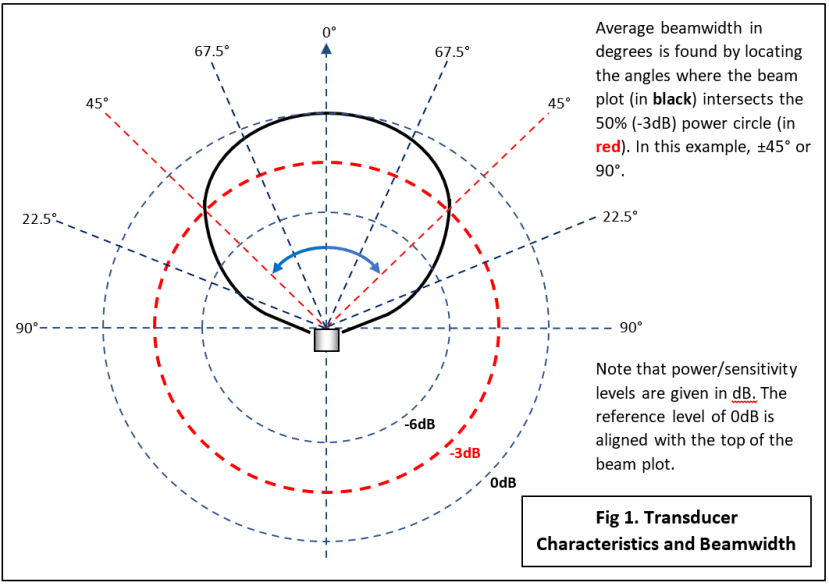
The thick black line is the device characteristic showing, unsurprisingly, that peak signal power and hence maximum detection range occurs directly in front of the transducer at 0°. This example is said to have a wide ‘beamwidth’ or low ‘directivity’. But how wide is ‘wide’ and can you put a number on it? This is where the concentric rings on the graph come in: they represent lines of equal signal power relative to the peak power at 0°. We define the outer circle going through the peak power point as 0dB. The inner rings represent lower power levels and where they intersect with the characteristic line, provide the relative signal strength at that angle. The average beamwidth for the device is defined as the angle when the power is 50% (or -3dB) of the maximum. Decibels are used to linearise the plot and keep it compact. The beamwidth for this example can be read off the graph as ±45° or 90°.
Transducer Characteristics
An ultrasonic transducer is basically a piezoelectric loudspeaker tuned to emit or receive a single frequency, usually 40kHz for operation in air. This ‘tuning’ means that if driven by a single pulse it will respond by resonating (or ringing) at 40kHz for a few cycles just like when a church bell is struck. That makes interfacing with logic simple! Frequencies up to MHz can be used in solid or liquid environments.
As suggested above, the sound does not emerge from the front of the device in an ‘ideal’ cone-shaped beam (Fig.2a), but spreads out with a wide beamwidth (Fig.2b) or narrow with side-lobes (Fig.2c), depending on the physical construction. The choice between wide and narrow beamwidth devices is largely determined by the application:
- Wide with relatively short range for basic collision avoidance. The system doesn’t need to know how big or small the object is – just that it’s there! The parking sensors on the back of a car are of this type. Typical value: 90° or more.
- Narrow with long range, able to resolve small targets close together at the same range. A robot vacuum cleaner may well use this type so it can ‘map’ a room in detail. Typical value: 30° or less.

The side-lobes in Fig.2c can be a nuisance at short range as they can make an object off to one side of the robot and not in the way, nevertheless appear as an obstacle.
Reflection Problems
Ultrasonic rangefinders make use of an effect called Specular Reflection whereby a beam of sound from a transducer is ‘bounced’ off a smooth surface perpendicular to the beam axis back to a receiver. If targets were always at right-angles to the axis of the beam, then distance measurements would be reliable and accurate. Unfortunately, they seldom are, and to make it worse the target material and position may be such that no signal is bounced back at all. Fig.3 illustrates some problematic situations. For illustrative purposes, the signal is shown as a single line, but in reality, it’s a lot more complex as we have seen in Fig.2.
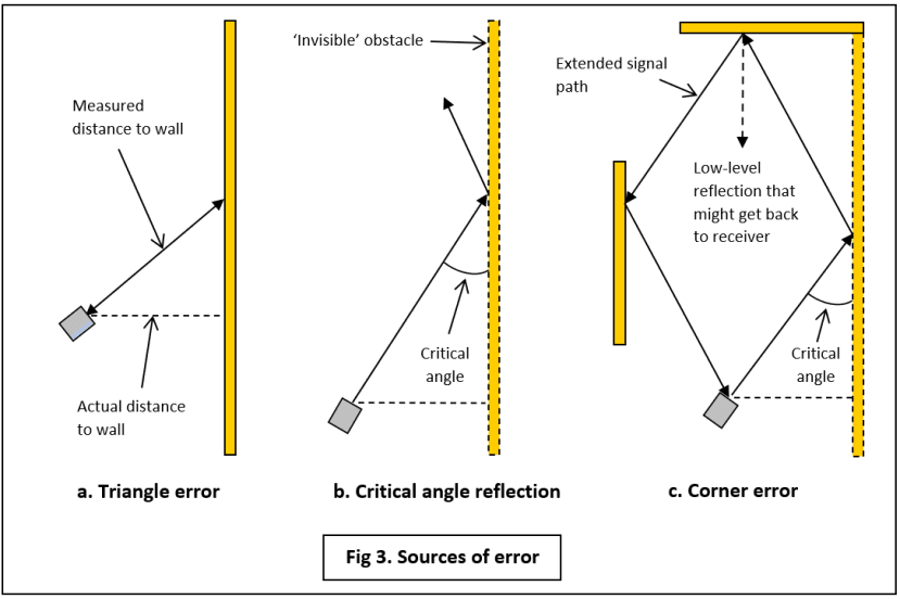
If the robot is heading towards the wall at an angle, then you can see from Fig.3a that the measured distance will be too long. As the angle with the wall becomes shallower, less and less signal is returned to the receiver as increasing amounts are reflected away. At a certain critical angle (Fig.3b), all the signal is reflected away from the robot. In other words, the wall disappears because there is no echo! This critical angle depends on the wall material and its surface: a very smooth gloss finish on a skirting board for example, can cause this effect. Slightly rough surface materials, such as cardboard cause the signal to be scattered in all directions no matter what the angle of incidence, so at least some makes it back to the receiver. This is known as Diffuse Reflection. Fig.3c shows how specular reflection at the critical angle in a corner can fool the sonar into making a very large error indeed.
The hardness of the target material is also an important factor. A skirting board will reflect most of the energy, absorbing very little, but soft furnishings (or trouser legs!) will do the reverse. This means that the maximum detection range is large for the walls, but soft objects may not be ‘seen’ until the robot is nearly on top of them. Note that this does not affect the accuracy of distance measurements, only the maximum range at which a particular object can be detected.
Rangefinders
Up to this point I’ve been describing ultrasonic transducers as transmitters. Fairly obviously a rangefinder needs a receiver and fortunately a transducer can do that too. The thing is though, just as an audio loudspeaker can function as a microphone, it doesn’t do it very well. You normally buy 40kHz transducers as matched pairs: the transmitter and receiver usually look physically identical on the outside, but inside they have been optimised for their respective functions. Typically, they will have the same basic part number with either ‘R’ or ‘T’ tacked on the end.
Unless you really want to make your own, it’s best to buy a rangefinder ready built. Price goes with sophistication of the on-board electronics. The Parallax Ping))) (781-3020) just has basic drivers and leaves all the measurement to a host MCU. On the other hand, the MikroElektronika Ultrasonic 2 Click module (184-0138) does all the hard work and outputs distance values on a UART serial channel. The Click module is an example of a Monostatic rangefinder which uses a single combined Tx/Rx transducer (Fig.4). This type is quite common now in applications that don’t require as high a performance as the Bistatic format. The main problem is a longer minimum range because the transducer can’t be switched from sending to listening until it has stopped ringing with the transmit burst. The pictured monostatic device is the Maxbotix LV-EZ4 (124-5448) .

Finally
In spite of all the issues outlined above, simple sonar will deliver cheap and effective room navigation for a mobile robot, albeit with multiple devices. For working outdoors over ranges longer than a few metres though, there is no doubt that ‘light radar’ or Lidar based on a scanning laser beam is the way forward. Thanks to all the development work in the field of autonomous vehicles, Lidar hardware is plummeting in size and price.
I had intended to describe in detail some of the software written for my twin-sonar FORTHdsPIC robot this time, but that will now be covered in future posts.
If you're stuck for something to do, follow my posts on Twitter. I link to interesting articles on new electronics and related technologies, retweeting posts I spot about robots, space exploration and other issues.