
Raspberry PI Revolution - KUNBUS Pi | Open Source IPC | DesignSpark

RevolutionPi_060736a152b2a76a7ca8b3edb728f4f87b1af21c.png

Open Source IPC based on Raspberry Pi

Is it an IIoT Gateway, DIN-rail PC, PLC or small control unit? Your call! Discover the world of "Revolution Pi".

This is part 1 of many posts where I explore the world of the Revolution PI, in this post I will review the various modules, their architecture, have a look inside and how to initially wire them finishing with a wired panel ready for experiments.

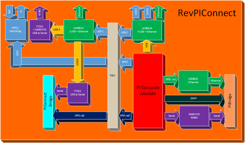
Please note that many of the included diagrams etc. have been created by me through examination of the schematics and architecture, there could be mistakes and if you see one, please let me know so I can correct it!

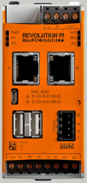
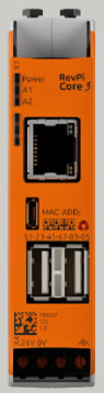
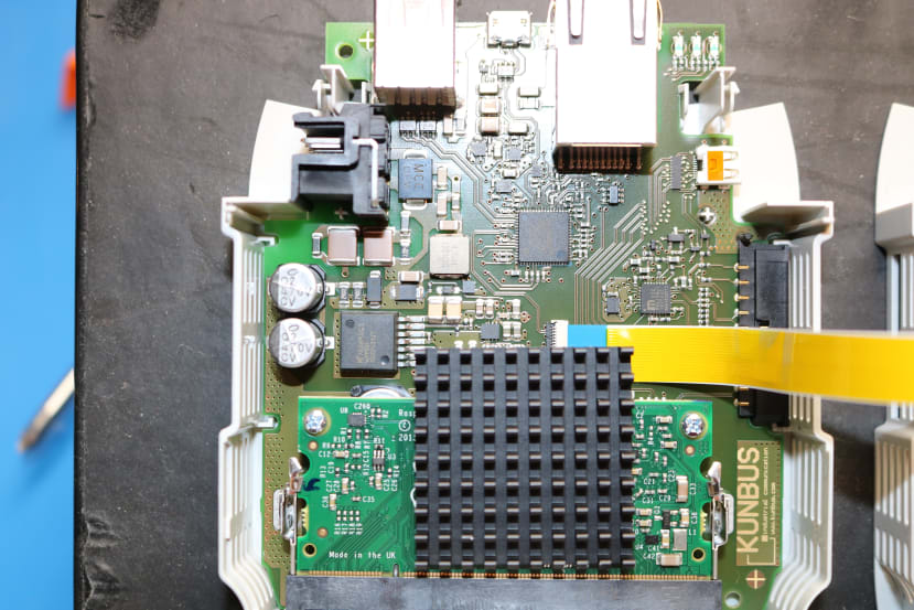
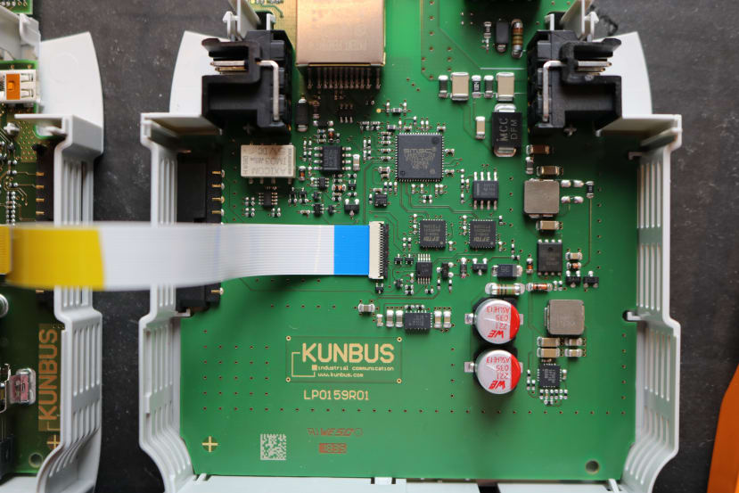
Controller based on the Raspberry PI 3 Compute Modules
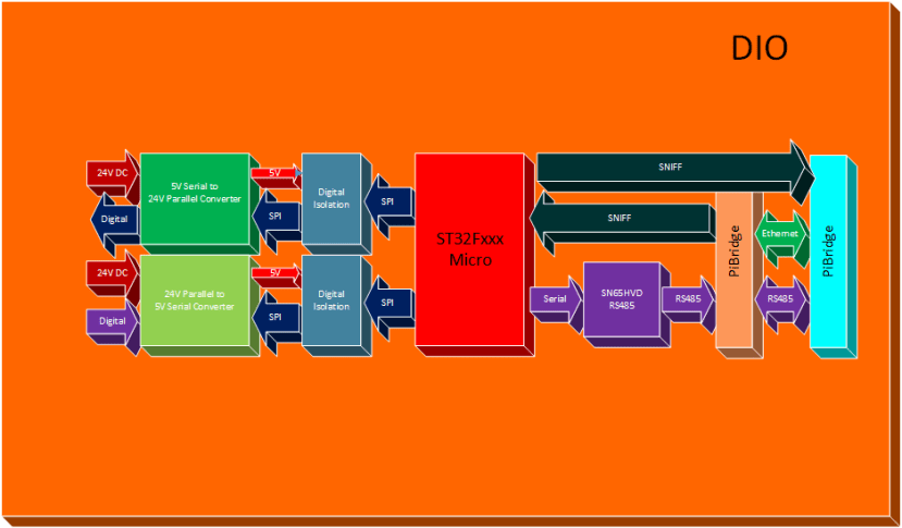
First thing of note is the fact that the Revolution PI Connect and Revolution PI Core3 are based on the Raspberry PI 3compute module.

The Compute Module 3 (CM3) is essentially a stripped down Raspberry Pi 3 (the BCM2837 processor and 1GB RAM) as well as a 4GB eMMC Flash device instead of an SD card.

The CM3 has a quad-core processor running at 1.2GHz. This is all integrated on to a small board which fits into a standard DDR2 SODIMM connector. The Flash memory is connected directly to the processor on the board most of the rest of the IO is made available through the SODIMM connector.

2019-01-22_0-57-35_20d702d2d45b3a90b1dbef352ff95677e6694eb5.png2019-01-22_0-58-36_46f97251fff629ea7a06f251997ae8de707cf6e7.pngIMG_0751_0a51ac5b13e2bed9b68aa498dac9e5443f1dfe44.jpg

The board below is only on the RevPI connect.IMG_0750_ec5a4ab6db90527afc656e7a6f1dd0ab6b2e758c.jpg

The motherboard (KUNBUS Design) adds at least 2 Ethernet controllers, real-time clock, 2 USB Ports and RS485 and an HDMI micro connector, one network port and one RS485 is used to communicate to other attached modules so they are not available to the user program. There is also a micro USB port but this is only used for programming.

On the Connect there is an additional Ethernet controller and RS485 ports that can be integrated into user apps. The connect version of the controller also adds a digital input pin and a single open relay output.

In the below diagram you can see the basic building blocks of the controller. For the Core 3, just remove everything to the left of the "FLEX".

RevPiConnect_3f98baf90fcaa07b44d5dadc1949ecb25463ba34.png

If you want to review the actual schematics, click RevPI Connect or RevPiCore.

Architecturally the Revolution Pi series follows a common approach to the processing of its IO, none of the external IO modules is directly available to the processor. In order to get or set IO value,s the program must interface through a device file and the underlying handler will send commends to and receive from the IO Module sub processors. These are all STM32Fxxx microcontrollers.

DIO Module

All versions (DI, DO, DIO) have galvanic separation between the PiBridge logic circuit and inputs/Outputs resp. (600 VRMS isolation voltage).

The RevPi DIO version has additional galvanic separation between inputs and outputs. All versions are protected against interference according to EN61131-2 requirements and may be operated between -40°C to 55°C ambient temperature with up to 80% rel. humidity.*

Overall cycle time is typically around 5 ms to 10 ms depending on system configuration but could be longer for a large configuration. This is the time it takes for a change in input or output to be realised in the memory of the RevPI controller, this happens using a background process that polls the modules to read values and writes to them when a change in the local device file is detected. This operating system is patched with a "Realtime Patch" in order to reduce jitter and variations in polling time as it is essential in industrial control applications that timing can be predictable.
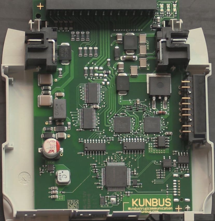
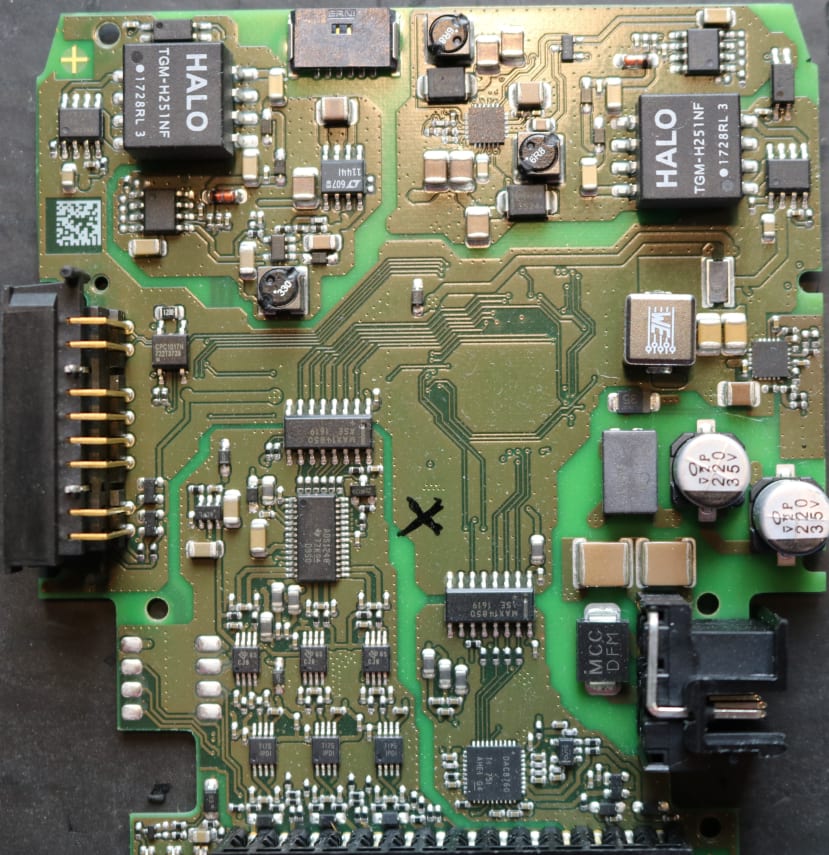
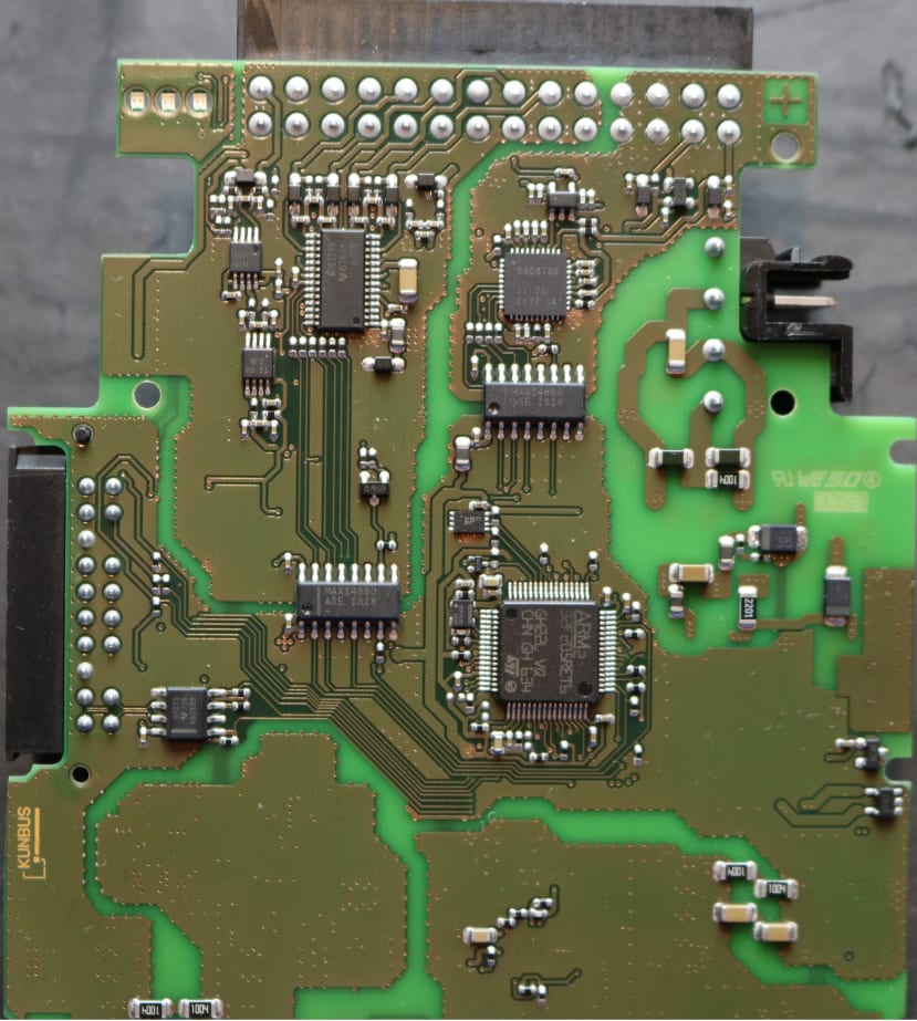
Here is the DIO Module block diagram:

RevPiDIO_d8545dd2e3ce1e0240de1059e18d0107dd72f32f.pngImage217_e19f055b2065f6b4ab96ae6c3842b6bda7a21540.jpg

As you can see, the Pi Bridge is used to interface with the module and the STM32Fxxx in turn will carry out the instructions for the core program and also independently manage the actual DIO pins, for example, if a pin is designated as an Encoder (Rotary Encoder used for CNC for example), the module will detect and retain the count for the core module, presenting the values as requested. The core application does not need to be burdened with the task of polling the physical pins. The same goes for outputs, if a pin is set to PWM, the STM32Fxxx will manage this too. The other point to note here is the complete isolation of the actual IO Pins from the STM32Fxxx and the main control module. This is why you see the additional 24V connections on the left of the diagram.

For the schematics, go to DIO and AIO.

AIO Module

For the Analog module, things are much the same regarding isolation, the STM32Fxxx controller and the autonomous processing. The biggest difference here is that the modules own 24V supply is used to drive the analog logic through the use of fully isolated DC-DC convertors and power regulation

Here is the AIO block diagram:

RevPiAIO_1e306ae3c10293bd650567e65b37a19af34229d9.png

This module supports 6 analog inputs, 2 Analog outputs:IMG_0757_db7e04b4b3b7a5d9b4f3d6f746b9dee96022bf41.jpgIMG_07561_ac2f994f72d87a73f2db9342c4a85676802d11d9.jpg

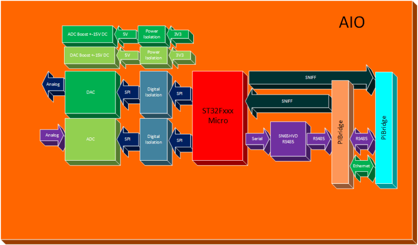
There is a wide range of configurations as you can see:

Voltage intput Current input Voltage output Current output


  • 0 – 5 V
  • 0 – 10 V
  • +/- 5 V
  • +/- 10 V


  • 4 – 20 mA
  • 0 – 20 mA
  • 0 – 24 mA
  • +/- 25 mA


  • 0 – 5 V
  • 0 – 10 V
  • +/- 5 V
  • +/- 10 V
  • 0 – 5.5 V
  • 0 – 11 V
  • +/- 5.5 V
  • +/- 11 V


  • 4 – 20 mA
  • 0 – 20 mA
  • 0 – 24 mA

RTD Channels

Besides 4 analog input channels, RevPi AIO also features 2 separate RTD input channels. The 2 RTD inputs enable temperatures to be measured with high precision from -165°C to +600°C in steps of 0.5°C using common RTDs sensors like Pt100/Pt1000 probes. The probes can be connected directly to the module with 2, 3 or 4 cables.

The last module I have is the Gateway Ethernet IP, I will dig into this module in another post as it will be a little more complicated.

So that's all the modules, then came the task of wiring them all up on a DIN rail based test board. This is what I ended up creating

IMG_0772_aafe152735d297e26ff2cc8a6f2ac0938f293012.jpg

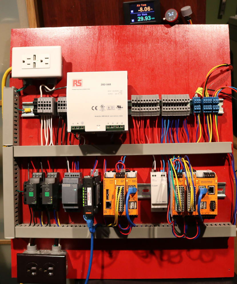
A simplified block diagram is as follows, all the RS part numbers are included in the diagram except the Kunbus modules as they're not available at time of publication, I will amend as soon as I have them.

RevPiTestBed_f55626e392fe330049240aa358fe59402b90bf0c.png

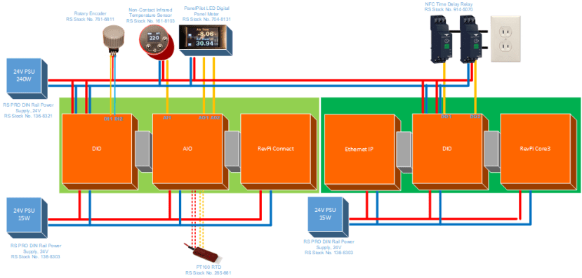
So in preparation for the next post, I have added the following

  • Lascar PanelPilot LED Digital Panel Multi-Function Meter for Voltage (704-8138)
  • RS PRO Non-Contact Infrared Temperature Sensor, 1m Cable, 0°C to 1000°C (161-8103)
  • RS PRO 4 wire PT100 Sensor, -50°C min +150°C max (028-5661)
  • Schneider Electric NFC Time Delay Relay (914-5070)
  • Bourns 24 Pulse Incremental Mechanical Rotary Encoder (781-6811)
  • Mean Well Power Supply, 24V dc Output Voltage, 10A output current (028-2568)
  • RS PRO DIN Rail Power Supply, 24V dc Output Voltage, 650mA output current (136-8303)

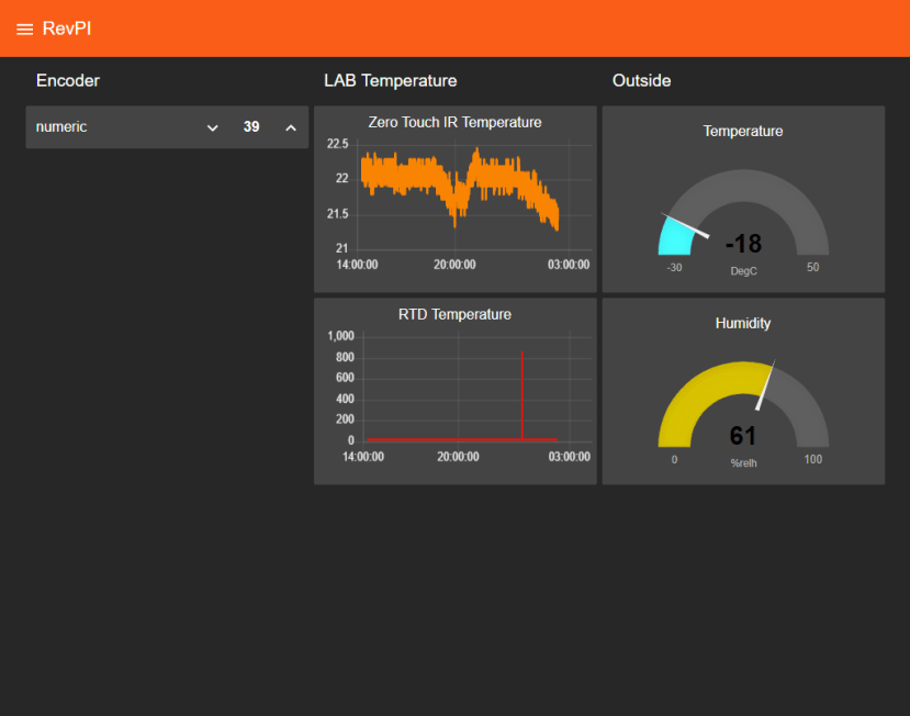
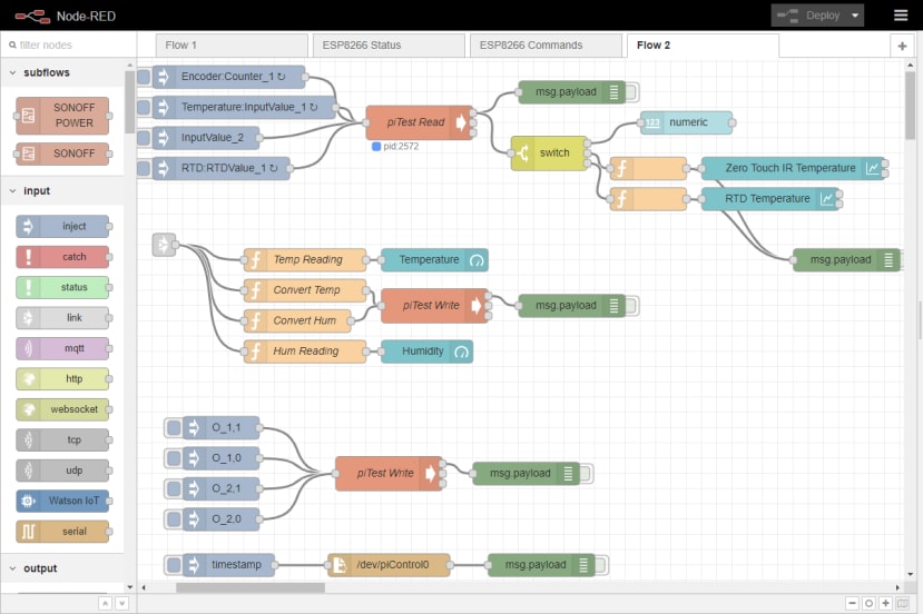
And to whet your appetite here is a taste of what’s to come:

2019-01-22_2-18-49_dc9fb883a73665c793b83004fc2a03216d31e7a2.png

2019-01-22_2-20-26_c721c0c54da6259486b4816e778b901bf2fb5bbb.png

With a background in Industrial Electronics, Solutions Architecture and programming, I now spend my time working on my YouTube channel ( https://www.youtube.com/thebreadboardca ) where I create educational videos showing how to use various devices including Test and measurement, Home and industrial Automation, Components and other fun things I am sent to review or include in projects. I will also create many projects to showcase the use of these items