Raspberry Pi 3 Smart Room Condition Monitoring
Follow article
 Dave from DesignSpark
How do you feel about this article? Help us to provide better content for you.
Dave from DesignSpark
Thank you! Your feedback has been received.
Dave from DesignSpark
There was a problem submitting your feedback, please try again later.
Dave from DesignSpark
What do you think of this article?
| Author | Dan |
| Difficulty | Easy to Moderate |
| Time required | 1.5 hours |
One of the baby steps in developing a DIY smart home system is to have an automatic environmental monitoring device. It is one of the easiest yet very useful projects for hobbyists and even for IoT engineers. In this project, we want to get familiar with basic Raspberry Pi tools and software. We want to develop a temperature-humidity monitoring device by using Raspberry Pi 3B+ and some sensors. The materials needed for this project are as follows:
Materials and components
- Raspberry Pi 3B+ (137-3331)
- 16GB (121-3897) – or 32GB (136-0148) – SD Card with Raspbian OS
- BME280 (184-5082)
- 5V3A USB power supply (909-8126)
- 7-inch Raspberry Pi display (111-5927)
Miscellaneous:
- SD card reader

Instructions:
STEP1: RPi OS installation
First, if you don’t have an OS-ready SD card yet, we highly suggest following these steps. If you already have one, please skip and go on to STEP 2.
1.1 Download Raspbian Buster OS from the Raspberry Pi website https://www.raspberrypi.org/downloads/raspbian/

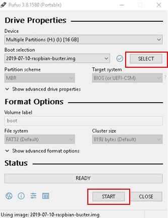
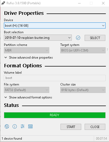
1.2 Insert your blank SD card to your SD card reader and plug it into your computer. Download an SD card flashing software such as Rufus (https://rufus.ie/). Using your desktop computer, select the Raspbian OS .img file (i.e. 2019-07-10-raspbian-buster.img). Next, flash the OS to your blank SD card by clicking START. Wait for up to 5-10 minutes for it to finish flashing the OS to your SD card.
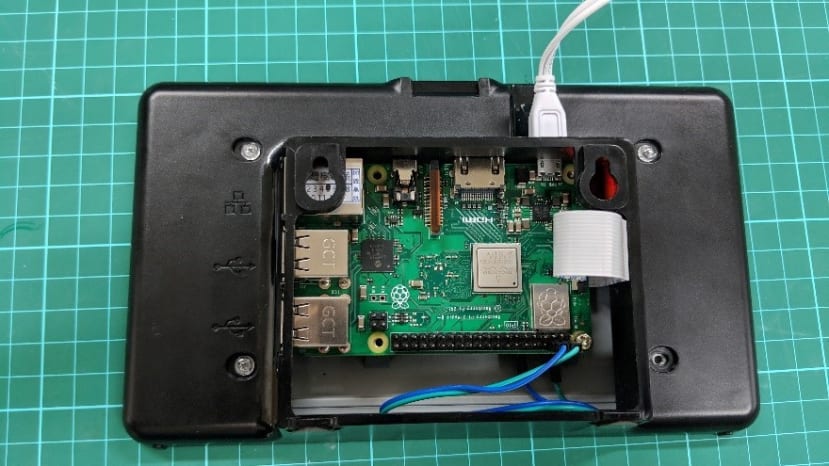
1.3 Once done, insert your SD card in the SD card slot of your Raspberry Pi. Connect your 7-inch Raspberry Pi display to your Raspberry Pi with your Raspberry Pi’s DISPLAY port. So that we won’t need to turn on the display separately, connect the 5V and GND of your display to the 5V and GND of your Raspberry Pi. This will make the display draw power from the Raspberry Pi instead.

1.4 Turn on your Raspberry Pi with the USB power supply.
1.5 Follow the on-screen instructions to set-up your Raspberry Pi.

STEP2: Preparing and connecting the hardware
2.1 In this step, we want to connect and test our temperature-humidity sensor. First, connect the BME280 pins to your Raspberry Pi as follows:
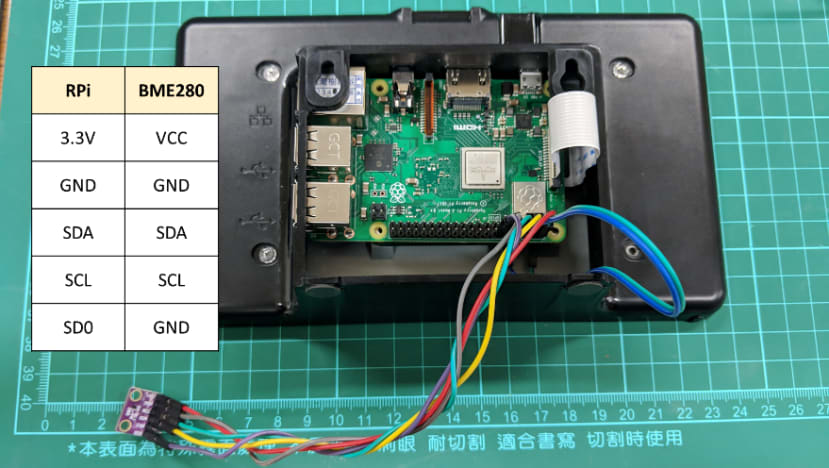
NOTE1: When buying the BME280 module, some of them don’t have soldered pins. If that is the case, try to solder them first with 2.54mm pitch male headers.
NOTE2: Some variants of the BME280 board modules have different size pin names. In other cases, SCL is named SCK, while SDA is named SDI. Moreover, SD0 is named CS in other boards.
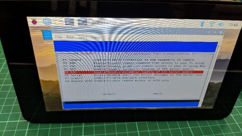
2.2 Enable I2C interface in your Raspberry Pi. This time, better use a USB keyboard to type in some lines to your Raspberry Pi terminal. Open your terminal then type in the following:
sudo raspi-config
After entering the above lines, it will show a selection window. Select the options in the following order: Interfacing options -> I2C -> Yes.

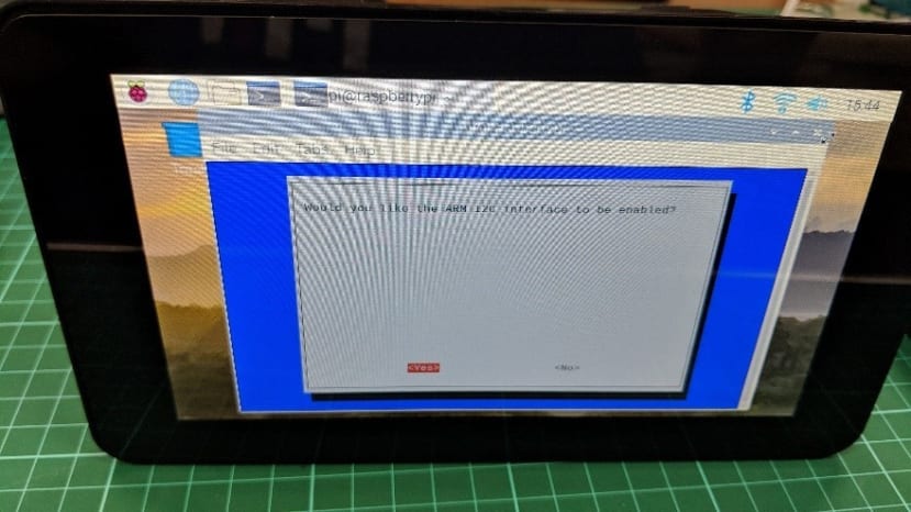
After doing so, go back to the initial screen and press Finish.

2.3 Now, it’s time to test if your BME280 sensor correctly connected. In the same terminal window, enter:
sudo i2cdetect -y 1If successful, you should be able to see the following output:

The command we entered shows all the connected I2C devices to the Raspberry Pi. In this case, we can see one device with an address 76 or 0x76 in hex. This is the unique I2C ID of the BME280. I2C is a very handy interface that can connect multiple sensors at the same time by calling their unique I2C addresses. If you cannot see the following output, recheck your wire connections.
STEP3: Install libraries and download codes
3.1 Before we head to programming the Raspberry Pi, we need to download and install some libraries. In this project, we want to use PyQT5, a GUI library for Python. Using your Raspberry Pi’s terminal, enter the following line:
sudo apt-get install python3-pyqt53.2 Next, install the BME280 and SMBUS libraries by entering:
pip3 install RPi.bme280
pip3 install smbus2
3.3 Download the program codes from our repository:
git clone https://github.com/danrustia11/CaveduRS
STEP4: Running the program
4.1 Since we already download the codes from the previous step, we run it with the following lines:
cd /home/pi/CaveduRS/RaspberryPi/SmartTH
python3 smart_th_gui.py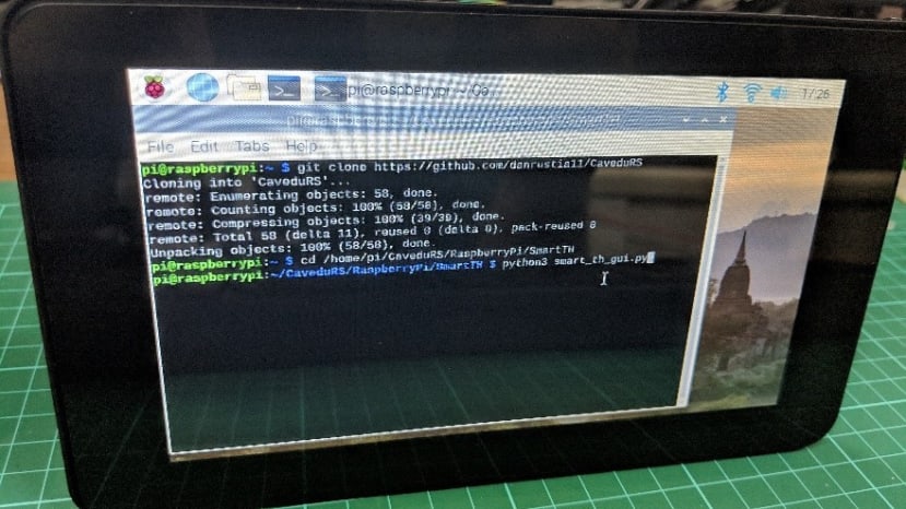
If nothing is wrong, you should be able to see the GUI on your screen.

NOTE: If you want to study the program codes, just open the file smart_th_gui.py then see the comments.
The GUI shows five pieces of information: time, date, temperature, humidity, and heat index. What’s special is the heat index. It is a value derived from the temperature and humidity that shows how our body actually feels depending on the temperature and humidity. This is a more accurate way of measuring room conditions as there are times that the weather is too humid or dry.
STEP5: Auto-run the program
Since you are now able to run the program, what’s left is to run it automatically when turning on your Raspberry Pi.
5.1 To do so, make a new file named run_th_gui.sh. This file is a Linux script file that is used to run several commands via terminal.

Afterwards, edit the run_th_gui.sh file by right-clicking the icon and clicking Text Editor. Once open, type in the following:
cd /home/pi/CaveduRS/RaspberryPi/SmartTH
python3 smart_th_gui.py
5.2 Next, make the script file executable by opening a terminal and typing in the following:
sudo chmod u+x *.sh
This will make all files with .sh as extension executable.
5.3 Lastly, we set which script file the Raspberry Pi will run after boot. We can do this by editing the autostart file of your Raspberry Pi. Enter the following:
sudo nano /etc/xdg/lxsession/LXDE-pi/autostartThen on the last line, input the following:
@lxterminal -e ./run_th_gui.shIn order for this to work, you should see exactly this kind of display:
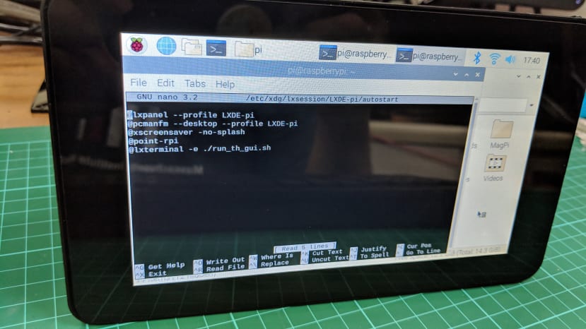
WARNING: Make sure you do not edit the lines above our added line or else it might affect the booting sequence of your Raspberry Pi.
After adding the last line, press CTRL+O -> ENTER -> CTRL+X
5.4 Finally, reboot your Raspberry Pi by typing in
sudo rebooton your terminal.
STEP6: Done
After rebooting, the Raspberry Pi should be running the program automatically and you will see the GUI display we have seen a while ago. If there is no problem, congratulations on your first step in building a DIY smart home system. Your finished project can be put on a desk, a cabinet or even hang it around your room to show the temperature, humidity, and heat index inside your room.