Overcoming the Limitations of Laser Diode Modules
Follow article Dave from DesignSpark
How do you feel about this article? Help us to provide better content for you.
Dave from DesignSpark
Thank you! Your feedback has been received.
Dave from DesignSpark
There was a problem submitting your feedback, please try again later.
Dave from DesignSpark
What do you think of this article?
Introduction
A laser diode module is a mechanical, electronic, and optical system built to contain, drive, collimate, focus, and sometimes shape the output beam of a laser diode. Laser diode modules offer several advantages over laser diodes alone:
- Low boresight error
- High pointing stability
- Optimised diode lifetime (e.g. electrical protection and more practical heat sinking)
- Convenient operation (e.g. easier mounting, analogue or digital control)
- Optical manipulation (e.g. collimation and line generation)
- Conform to a laser safety class (IEC60825-1) by accurately setting output laser power
However, laser diode modules have inherent limitations. This technical note explains common limitations and how system integrators (OEMs), researchers, and end-users, in general, can overcome them.
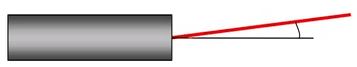
Boresight Error
Boresight error is the angular difference between the output laser beam (beam axis) and the laser diode module housing (mechanical axis). This angle is typically caused by a tilted diode TO-Can inside the module housing, or a tilted laser chip inside the diode TO-Can (TO-Can, also known as just “Can”, is a type of outer casing for the laser diode chip). The beam is then incident on subsequent optics off-centre and at an oblique angle and finally exits the module. As a result, there is a difference between the expected and actual position of the laser beam on a surface, and this difference increases with increasing working distance.
In certain laser diode modules, it is possible for manufacturers to fine-tune the boresight error before components are fixed in place with an epoxy resin (“potting”) or similar substance. Other specialised modules may be fitted with adjustment screws that allow users themselves to fine-tune the boresight error to zero.
A laser diode module with low boresight error is typically recommended for long-distance targeting and sighting applications, or applications that require particularly precise positioning at short-to-medium working distances. A module with adjustment screws is typically used to correct the boresight error after the module has been installed in a system.
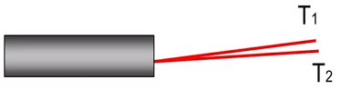
Pointing Stability
The beam pointing stability of a laser diode module quantifies the angular fluctuations of the beam direction. Such fluctuations are primarily caused by background mechanical vibrations and thermal expansion/contraction (“thermal drift”) of the module structure (e.g. housing, lens holder).
Thermal drift is caused by the heat generated by the laser diode itself, in addition to electronic components aboard the drive circuit during operation. Maintaining a stable operating case temperature typically reduces thermal drift (if used within the device’s specifications). Heat is removed from the module via the housing by mounting the module on a suitable heat sink. Another method involves cooling the module using fans, or Peltier coolers for more precise temperature control (thermoelectric cooling (TEC)).
It is possible to isolate laser diode modules from ambient mechanical vibrations caused by foot traffic, fans in a laboratory, a local road or railway, etc. Known as “vibration isolation”, this can be achieved by mounting the module on a tabletop or desk with air-sprung or self-levelling isolators (e.g. passive or active feet/legs). The technology damps oscillatory motion generated by ambient mechanical vibrations with the aim of increasing pointing stability.
It may not be possible to completely remove beam pointing fluctuations at the source. If this is the case, one or a number of piezo-actuated mirrors can be placed in the beam path. A position-sensitive detector (PSD) can then be used to monitor the position of the reflected beam. This information can then be sent back to the piezo-actuated mirrors which then move to correct the direction and position of the beam.
Laser Diode Lifetime - Electrostatic Discharge (ESD)
Static electricity is the result of an imbalance between negative and positive charges in an object. Negative charges (electrons) can build up on the surface of an object until they find a way to be released or discharged. This can occur when the object makes contact with another electrically charged object. The release of such charges causes an instantaneous flow of electric current (“Electrostatic discharge (ESD)”). Laser diodes are highly sensitive to static electricity and are susceptible to damage by ESD.
Manufacturers can equip laser diode modules with features that protect against ESD. For example, the drive circuit inside the module housing can be grounded to the laser diode Can. Additionally, filling the empty space inside the module housing with potting (an epoxy resin similar substance) that surrounds the drive circuit and Can will provide more resistance against the flow of electrostatic current.
Nevertheless, mishandling a laser diode module could still cause ESD and reduce the laser diode’s lifetime. When handled and stored correctly, the specified laser diode lifetime can be achieved and often exceeded. The following measures should be taken by the user to avoid damage by ESD:
- Use laser diode modules with electrically isolated housing
- Wear an anti-static wrist strap
- Install a grounding mat
- Apply anti-static spray to desktops or workbenches
Laser Diode Lifetime - Maximum Ratings and Power Surges
Operating a laser diode outside of its specifications can significantly reduce its lifetime. Unprotected power outlets, for example, can cause instantaneous voltage spikes (“surges”) that exceed the maximum voltage rating of a laser diode. Due to their fast response times, laser diodes are highly sensitive to surges and can be damaged as a result.
In order to achieve or exceed their specified lifetimes, laser diodes require precise control of operating current and voltage. To protect against unexpected or accidental operating parameters, the drive circuit aboard laser diode modules can be installed with overvoltage and overcurrent protection features, in addition, to reverse voltage polarity protection. It is also good practice to use surge-protected and current-limited power supplies.
Laser Diode Lifetime - Mounting and Heat Sinking
As mentioned above, the laser diode itself can generate heat during operation. Excessive heat can affect the diode’s operating voltage or current range, increasing the risk of exceeding its maximum ratings.
In general, the lifetime of a laser diode statistically doubles for every 10°C decrease in operating case temperature and vice versa (within the specified operating temperature range). Laser diode modules should be mounted on a suitable heat sink to effectively remove (“dissipate”) heat from the module via its housing. The more surface area in contact with the heat sink, the more heat will be dissipated. Lifetimes can be extended by maintaining the case temperature at the low end of the operating temperature range.
Non-Uniform Lines
The light emitted by a laser diode is typically divergent. For this reason, a collimating lens is installed in a laser diode module to collimate or focus the light. The resulting laser spot can be converted into a line by installing a line-generating optic (LGO) after the collimating lens. The intensity distribution along the laser line depends on the type of LGO and its alignment with the collimated beam.
A cylindrical or rod lens is an LGO that generates a Gaussian intensity distribution along the length of the line. A Gaussian line has a “hot” centre and fading ends i.e. non-uniform intensity distribution. Other non-uniform lines can also occur as a consequence of optical misalignment, that is, if the collimated beam strikes the LGO off-centre or at an oblique angle. Non-uniform lines can be acceptable in beam detection or visual alignment applications where the main requirement is a visible or detectable line regardless of the intensity distribution.
However, Gaussian and other non-uniform lines are typically unsuitable for use with machine vision cameras in applications such as 3D laser triangulation. If the light intensity interacting with a target object or surface varies at different positions along the length of the line, some pixels would receive too much or not enough reflected light. Errors can result, and the camera and image processing software generates an inaccurate representation of the target surface.
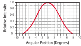
A Powell (“prism”) lens converts a collimated laser beam into a line with an approximately uniform distribution of energy in a specified central region. It achieves this by generating spherical aberration that redistributes the light along the line. Compared to Gaussian distributions generated by cylindrical/rod lenses, the amount of light in the central region is decreased while light at the line's ends is increased. The relative intensity typically varies by ±15-25% within the central region. This is known as “uniformity”.
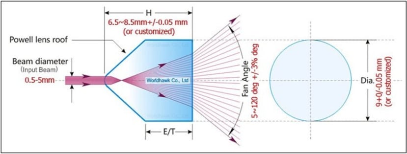
Laser diode modules with an integrated Powell lens are typically used for triangulation because the amount of light interacting with the measured surface does not vary significantly with position along the central region of the line. They also have well-defined line ends that can be more easily detected by a machine vision camera compared to the faded ends of a Gaussian line.
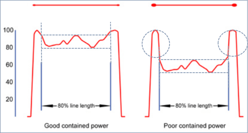
Intensity Peaks at Line Ends
Uniformity is typically measured in the central 80-90% of an illuminated laser line depending on the Powell lens being used. The total power contained in this central region determines the peak power at the line ends. Powell lenses that don’t redistribute enough light to the central region produce intensity peaks at the line ends. As a result, the laser safety classification will increase because it is based on the highest power value.
A typical Powell lens has an aspheric ridge (“apex”) across its diameter. When a collimated beam is incident on the apex, the light is redistributed and converted into a line through spherical aberration. As uniformity is typically more useful than intensity peaks in machine vision applications, high quality and well-aligned Powell lens will typically maximise the power contained in the central region of the line and take full advantage of the laser’s available power.
Other approaches to improving line uniformity include:
- Truncate a laser line spatially using an aperture, thereby transmitting only the central region.
- “Flatten” the intensity profile of the line using a diffuser or tophat generator.
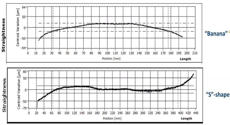
Line Straightness
Line straightness is a measure of the deviation of a line from its best linear fit. In practice, the tilt of the laser diode can/chip, surface imperfections, unit-to-unit variation, or thermal drift can misalign optical components. If the incident laser beam strikes the LGO at an oblique angle and/or off-centre, the laser line becomes curved. This typically occurs on the micron scale.
The apex and exit face of a Powell lens should be manufactured and installed in the laser diode module such that they are perpendicular to the incident light. Additionally, manufacturers can increase line straightness by ensuring that the collimated beam is incident with the centre of the LGO. Some system integrators take into account line straightness during system calibration to minimise the impact of line curvature.