Multifunctional Robot
Follow article Dave from DesignSpark
How do you feel about this article? Help us to provide better content for you.
Dave from DesignSpark
Thank you! Your feedback has been received.
Dave from DesignSpark
There was a problem submitting your feedback, please try again later.
Dave from DesignSpark
What do you think of this article?
The aim of this project is building a “MINI-SUMO” robot which will be able to fight against another robot in an autonomous way and push the other robot out the dohyo, as in the traditional sumo fight. Besides, it will have two more operating modes: LINE FOLLOWER and REMOTE CONTROL, in these modes, the robot will be able to follow a black line outlined on a white surface and it can be remotely controlled by means of a Bluetooth device. Below you can see an explanatory video about these three operating modes:
For the development of the robot, a basic knowledge of four different fields is required: electronic circuits, PCB design, microcontrollers and 3D modelling. Nevertheless, there is no need to be an expert, and throughout the development of the project, the necessary skills and knowledge will be acquired. The description of the whole project will be divided into three main blocks.
1. Electronic circuit design
To design our robot, we must bear in mind the different specifications that must be fulfilled for the correct development of the project, as the official rules of robot fights, for example, that this project also includes:
- Max robot size (10cm x 10cm, no height limitation)
- Max weight: 500 grams.
- Max Budget: €50, (excluding PCB manufacturing)
- A general START button
- CONTROL: PIC microcontroller
- SENSORS: close/far range infrared and ultrasound sensors
- MOTION: DC motors
- The robot must wait 5 seconds before the combat starts (BATTLE MODE)
- POWER SOURCE: 8.4V, 150mAh rechargeable batteries
From the aforementioned specifications we can obtain a BATTLE MODE robot; besides, if we want to add the other two operating modes we’ll need to use the different components (below there is a brief explanation of each component):
Microcontroller:
The microcontroller governs the behaviour of the robot. More details about this component can be found in the Programming Environment part. In order to connect the PC with the microcontroller and enable direct programming/debugging of the robot a modular connector is essential, as well as some of the components required for the connection.
Linear voltage regulator:
To power our robot we have a rechargeable battery of 8.4V and 150mA/h. However, to power the whole signal circuit, both sensors and the microprocessor, we need a 5V constant voltage. Thus, we have used a LM7805 voltage regulator. Besides, this device is able to provide up to 1A current, so this is more than enough to power our circuit.
The connections needed to obtain the voltage are the following (C is a set number to ensure a stable voltage).
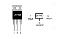
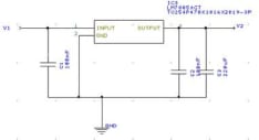
Figure 1. Linear voltage regulator
CNY70 Short distance infrared sensors:
These infrared transducers are ideal for black and white detection: they will both detect the limits of the ring and the black line in its LINE FOLLOWER mode. Here you can see the circuit:
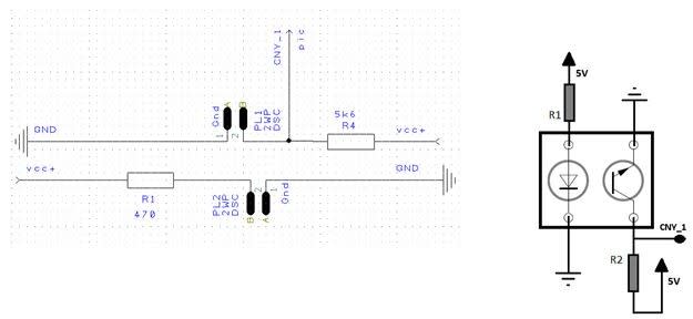
Figure 2. CNY70 connections
There are two different outputs depending on the colour of the surface that the sensor detects:
- Light surface: the transistor is saturated and lets the current through, so the output is GND (0V).
- Dark surface: the transistor is cut-off, so the output is 5V.
SHARP long distance infrared sensors:
To detect its rival in the MINI-SUMO mode we will use a long distance reflecting sensor. This device does not need any kind of conditioning and it changes the output voltage depending on where the opponent is; the maximum detection distance is 30cm approximately.
Figure 3. Long distance infrared sensor
Ultrasound sensors
In order to avoid failures when the robot detects its opponent, long distance ultrasound sensors are used.
To detect the distance these sensors send a series of pulses that bounce against a surface, return to the sensor and are captured by the receiver. The distance between the robot and the surface is proportional to the time it takes to complete the process. If there is no signal after a certain period of time it means that there is no object in its field of vision.
This device has all the conditioner circuit incorporated, so you can connect it directly to the microcontroller.

Figure 4. Ultrasound sensor
Bluetooth module
This device, together with an Android application, is indispensable to remotely control the robot with a mobile device; all this will be explained in the section Programming Environment. To correctly use this module, it’s necessary to connect the transmission pin Tx of the module with the pin which received the data in the PIC (Rx), and the receiving pin Rx of the module with the transmission pin of the microcontroller (Tx).
DC motors and motor driver.
The motors chosen have a reducer in order to get more strength at the expense of reducing the speed. To control these motors we have the device L293D, which decides whether the motors will run forward or backwards, using diodes connected to the maximum voltage supply or ground. Here you can see the connection between the motors and the driver.
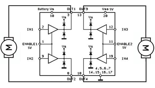
Figure 5. Driver connection
RBG LED
In order to visually show the robot’s performance, we will use RGB LED: blue will indicate that we are on the REMOTE CONTROL mode, green will be used for the LINE FOLLOWER mode and red for the MINI-SUMO mode. The resistors shown in the following figure are necessary to limit the voltage in the LED. They have been established for 20mA approximately, so this is the conditioning circuit:

Figure 6. RGB LED
Piezoelectric buzzer
This component reproduces the music programmed in the microcontroller, but we didn’t have enough time to program it. If you want to use it you only have to adjust the duration of the pulse because each musical note has a different frequency and therefore a period.
Eventually, to be able to develop the project, we need the following components:
- ON/OFF Switch
- An LM7805 linear voltage regulator
- Two infrared sensors CNY70 located at the front, very close to the floor
- An ultrasound sensor HC-SR04 and a reflecting sensor SHARP GP2Y0A41SK0F
- PIC16F886
- One modular connector RJ11
- One Bluetooth module HC-05
- One motor driver L293D
- Two DC motors, one on each side
- Two RBG LED
- A piezoelectric buzzer
- A steel ball bearing, the support point at the front
- Battery connectors
- Several resistances and capacitors
2. PCB design
When the electrical circuits are designed, it’s necessary to translate them into a PCB design. We have used the DesignSpark PCB 8.0 software. For this part, we have created a Design Technology with specific spacings, track thicknesses, pads styles, etc. Afterwards, the components are placed on the board following PCB design considerations to try to make the connexion of the different components easy. To reduce the number of tracks and vias, the top layer is used as 5V plane and the bottom layer as GND plane. The following figure shows a 3D representation of the PCB. The full DesigSpark PCB design project has been attached at the end of this article.
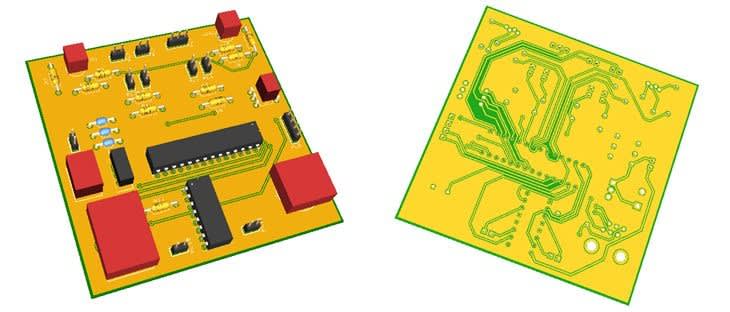
Figure 7. PCB design
3. Programming environment
Microcontroller
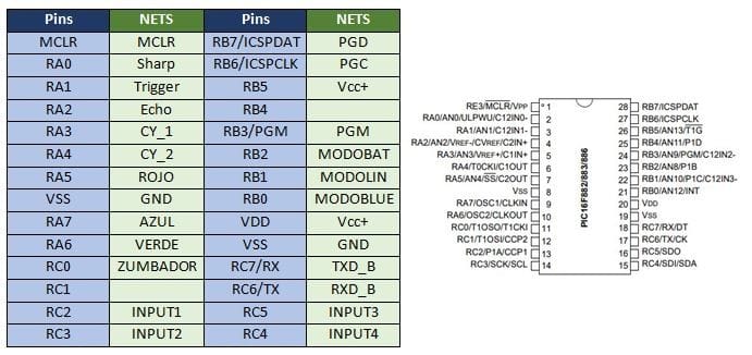
The microcontroller used in this project is the PIC16F886. The main reason for this microcontroller selection is that it has enough pin count, a serial connection module for the Bluetooth, and has an internal oscillator, which reduces the number of connections and errors.
The connections between the microcontroller and the different devices are shown below:
The microcontroller has been programmed using the software MPLAB X and the ICD3 as a depuration tool. The language of the programme is C, and the code is very easy to understand the development of the program. This code has been attached at the end of the article.
The MINI-SUMO and LINE FOLLOWER modes are automatic, which means that when choosing one of these options the robot will run the program and its movements can’t be directed. The only possibility is to stop it whenever the user wants to.
Mobile Phone App
For the Bluetooth control you need to install an application on your mobile device; by means of this application, you will be able to choose the character sent to the robot and, therefore, the task that the robot will perform. We have chosen the app Arduino Bluetooth because we think that this is the most comfortable application for this kind of control. Here you can see the screen with the buttons to control the robot and the characters that the mobile phone sends via Bluetooth to our device depending on the button we press.

Figure 9. Arduino Bluetooth interface
In the following table you can see the task that the robot performs depending on the character chosen from the mobile phone:

4. 3D Modelling
We have designed a casing (by means of a 3D Printer and the programme SolidWorks) to implement the whole circuit and to provide a place to locate and protect the different devices and the PCB. This is the 3D model:
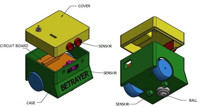
Figure 10. Case 3D model
We have strategically incorporated some additional materials, such as lead, to adjust the weight and increase stability. Besides, the final design has an aluminium front plate at ground level specially designed for combat.
Comments
At first sight, creating a robot step by step may seem difficult but, in fact, you can learn a lot of things throughout the project.
I hope that after reading this memory you now feel the urge to make your own robot and even to try to improve the robot described in this article.