*WINNING ENTRY* DesignSpark Leak Killer Challenge: Smart Leak Detection System with Sensor Network
Follow article
 Dave from DesignSpark
How do you feel about this article? Help us to provide better content for you.
Dave from DesignSpark
Thank you! Your feedback has been received.
Dave from DesignSpark
There was a problem submitting your feedback, please try again later.
Dave from DesignSpark
What do you think of this article?
Hello, my name is Josh and I am a recent electronic engineering graduate currently enjoying my second year in industry. The DesignSpark Leak Killer Challenge was an interesting change of pace from my usual portfolio of home-made robots and was exciting to research and develop a practical solution for a real-world issue; to protect domestic environments from potential water damage by utilising smart-system design and Pycom’s novel IoT style hardware.
Finding a practical solution to the challenge was an extremely involved activity as it presented no obvious and immediate answer and despite my thorough research, there were not many available systems to directly derive inspiration from. This was to be expected to some degree but even the results that I did come across only solved very specific issues, rather awkwardly and in some cases, unreliably.
The aim of my design was to create a comprehensive solution that was feasible to mass-produce using cost-effective components, while still maintaining maximum reliability of the system hardware and software as well as aiming to use modern smart/IoT style design themes. I have documented my design process and solution to the three challenge requirements below in hope that the system will be of inspiration to Legal & General and the wider DesignSpark community.
Leak Detection System Overview and Development
The video above details the direction I took having read the design brief a few times over and subsequently spending a lot of long weekdays after work to realise my idea. The section below will detail the main subsystems and my respective thought processes that lead me to my solution.
Localising Leaks with Novel Moisture Sensor Networks
The project’s first consideration in my case was how to detect potential leaks in the forward water pipe system as it enters the home from the wider outside infrastructure. After some consultation with a plumber and an instrumentation engineer, I realised that I could use a flow sensor to monitor and profile the water but would still not provide a solution for diagnosing the cause of any flow anomalies and localising where they had occurred. A decent solution then it seems would be in the form of combining flow meter readings and dedicated leak detecting sensors.
I considered using wireless sensor networks to collate this data for the monitoring system but having researched the price of wireless transceivers such as ZigBee and Wi-Fi I realised this would raise the cost of the system significantly and thus concluded that a wired network would be best and more secure. The pivotal requirement for the network would be reliability and minimal wiring so I needed to choose a technology that would accommodate these elements. This involved using some sort of serial network that has a decent range and noise reducing capabilities. I considered using RS485 as it has the range and noise suppression required but then I realised that there was an existing proven solution that was very similar in application.
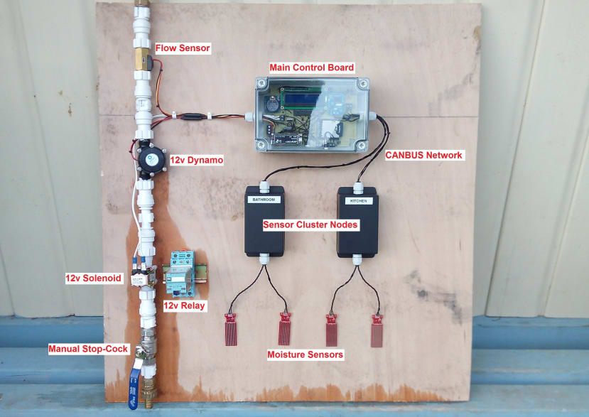
I derived my idea from the high-reliability systems used in vehicle diagnostic and communication networks that use CANBUS to exchange data over a rugged "mesh" style network infrastructure. Much like these networks, I decided to have a cluster of sensors attached to each node to reduce wiring, with a unique network node ID. This node can then report any leak sensor errors to the main circuit board which can then isolate the water supply and electrical mains. Each node can be assigned to a specific room where individual sensors on the node will detail exactly where the leak is in the room e.g. under a boiler or sink, similar to how a car has standard IDs and diagnostic codes. Using this method reduces the amount of wire needed to one twisted pair which makes the installation a lot cheaper and simpler than using wireless sensors and can even have redundant wire routing for extra reliability. Each node is also hot-swappable, being able to find an unused ID slot on the network dynamically through an ID querying function programmed into each microcontroller. By default, the master is ID 10 and each node will dynamically find and assign its own ID starting from 11 when the user pushes the button on the circuit-board.
Leak Monitoring System Motherboard
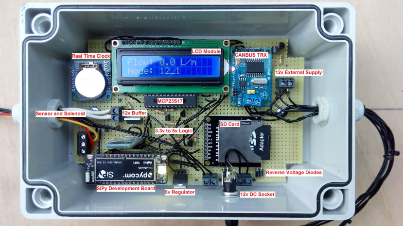
My choice of logic controller for the system was the SiPy development board that was mentioned in the challenge brief. I was impressed with the number of different integrated IoT elements the board utilises, most of which I was planning on using in my build anyway. There were a good number of teething issues throughout the development due to plugin updates and an incomplete API and documentation. I also needed to learn Python with its unintuitive syntax and overcome the 3.3v to 5v logic issue. Despite this, I managed to produce the main board hardware that underpins the flow monitoring algorithms provided by the SiPy board, seen below.
Flow control and monitoring
The SiPy code begins by monitoring the system water flow via the rising edges provided by the hall-effect flow sensor to a logical input pin on the development board. This can then be used by a number of other software functions including the maximum flow and trickle-flow threshold watchers, isolating the water flow and electrical mains when their trigger conditions are met, with the solenoid and relay respectively. The LCD screen also displays this data for the user to monitor manually through the transparent enclosure, much like a normal flow meter.
It is worth noting that I have used an intrusive sensor and solenoid as placeholders for my non-intrusive solutions that were developed in parallel with the main circuit-board. Using placeholders guaranteed I had a fully working system to demonstrate at the end of the project even if my non-intrusive systems failed to work.
Time-based water flow profiling
The passive flow profiler function makes use of the SD card socket and real-time clock module to log average flow data over time and save it to an array of text files. The logging period is currently 24 hours but could be expanded to monitor data over years. The data is written to the text file in a comma separated variable format, meaning it can be imported into an Excel file and graphed against time for further interpretation by the user at a later date.
CANBUS node error listener
Another function of the motherboard is to listen on the CANBUS network for sensor cluster nodes returning any error conditions caused by moisture in their local environment. This data is read by the intricate MCP2515 backend code modules and is stored as a variable to be printed to the LCD screen upon update. The user can then use the node ID and sensor number data, to locate and troubleshoot the leak. Any node errors will trigger the water and electrical mains isolator. These errors are also saved to a directory on the SD card with a time stamp provided by the real-time clock.
Other hardware notes:
The motherboard and sensor nodes take a standard 12v DC input which is supplied by a common 12v wall adapter in my documentation but is also designed to accommodate battery inputs such as 12v lead-acid or 11.1v lithium technologies. The system also provides a form of regenerative water-power from a 12v dynamo unit connected to the pipe assembly. This is designed to decrease the power consumption and support the use of batteries via the reverse voltage diodes, thus elongating its operating lifetime.
It is worth noting that despite the requirement to run on remote power, system elements such as wireless transceivers and valve actuators will deplete any stored charge in an inconveniently short time-span, hence my design includes both mains and battery compatibility. This will also need to be considered if the designer also later wants to utilise the Wi-Fi and SigFox network adapters integrated in the SiPy development board.
Most of the sub-system logic runs on a regulated 5v DC derived from the 12v DC mains input. The SiPy makes it awkward to interface with a lot of components as it is powered with 5v yet runs on 3.3v logic and requires voltage buffering up to 5v logic.
The enclosure was chosen specifically for the application environment i.e. water based, and as such has a good IP rating, backed up with the use of lid seals and IP67 cable glands for when it is eventually splashed… which it was… a lot. It is worth mentioning that the enclosure was chosen to facilitate the use of the LCD screen without compromising the ingress protection of the circuit board, hence the transparent lid.
Android App
In the interest future proofing for later use in smart/IoT system environments I also designed an Android app with the intent to extend any current system functionality with the addition of a user-friendly interface to display further information in a way that would be familiar with the modern consumer. The app uses classic Bluetooth which is common to all smartphones and uses less power than the alternative Wi-Fi network and is, therefore, more preferable when both connected ends are running on battery power. I was planning on using the Pycom Bluetooth API code library but it currently only supports Bluetooth-LE for some reason, so I was forced to execute this functionality with a standalone Bluetooth transceiver on the main board.
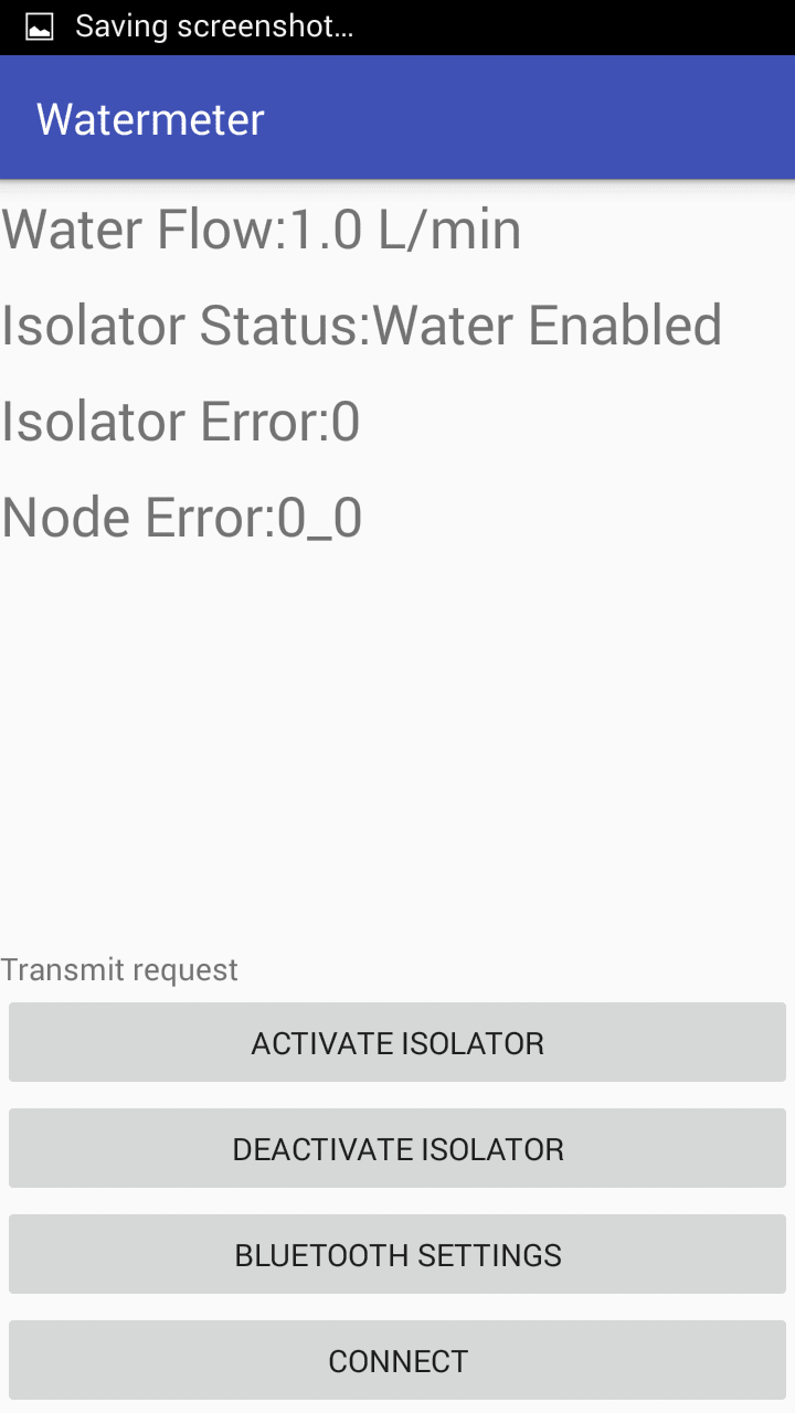
The aesthetics are something to be desired but in efforts to demonstrate the app’s capability to extend any core functionality, I included some basic telemetry data from the leak-detection system as well as demonstrating user control functions by overriding the water/electrical-mains isolation from the phone. As a basic alpha build it presents a good example of what could be implemented and developed on in the final system design chosen by Legal and General.
GitHub Repository
All of my code can be found on my GitHub repository and is all implemented using an open-source design mentality, making it easier to develop further in their respective IDEs i.e. Visual Studio Code/Atom, Arduino/Atmel Studio and Android Studio.
I strongly encourage anyone to please explore my work to truly appreciate the effort required to achieve the results seen in my system. I have written everything from scratch in languages including Python, C++ and Java, which amounts to 2420 lines of code.
There are a number of “backend” modules that I have developed specifically for the design challenge including the CANBUS, RTC and LCD elements as well as other lower level integrated circuit interfaces such as the MCP23S17 and MCP2515.
The frontend has been implemented in main.py although it could have a separate Python module in its own right. The frontend combines the functionality of all the backend module functions into a fluid update loop that demonstrates its potential to monitor leaks in a domestic environment using the intuitive functions seen in the main file.
Non-Intrusive System Development and Research Documentation
Non-Intrusive Flow Sensor Development
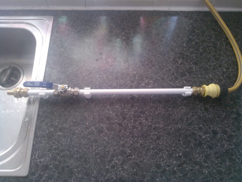
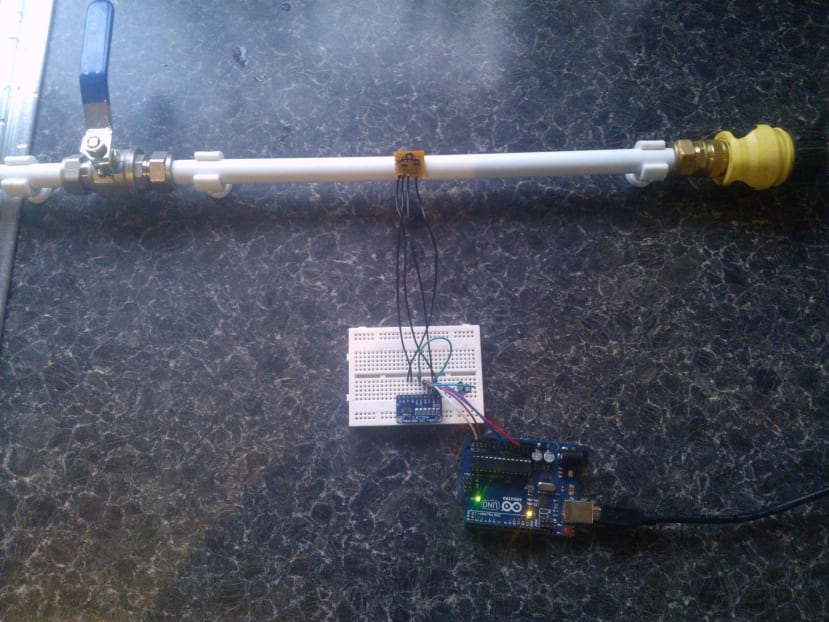
The flow sensor development was the most challenging and time-consuming element that was faced in the build. The requirement of a non-intrusive sensor led to some quite extensive experimentation and testing with the custom pipe assembly seen below.
Research suggests that the most common form of measuring flow in a pipe is by using acoustic principles often in the ultrasonic spectrum. With this in mind, I tried to recreate these principles using the most cost-effective methods and with non-proprietary components/technologies.
Ultrasonic Time-of-Flight Sensor Development
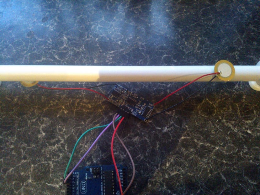
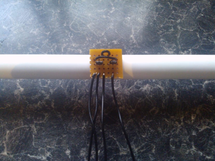
One of the most common methods of flow measurement is to use an ultrasonic time-of-flight sensor to measure the acceleration of sound impulses caused by the moving medium in the pipe i.e. water. In order to recreate this principle, I used the openly available and very common HC-SR04 ultrasonic time of flight sensor. By modifying the piezo elements with custom pads I was able to mount them on the pipe assembly to measure sound through the solid medium.
The problem with this principle is that the speed of sound in water is ≈1500 m/s compared to air ≈350 m/s and there is also a very small distance between the sensors on the pipe, of around 0.2m. Giving a propagation time of 0.2/1500 = 133.3333333 us which is possible to measure. However, considering the relative velocities of sound in water, to the speed of the running water, the time-domain resolution required is suddenly extremely high.
At an assumed water flow of 0.2m/s, the speed of sound will be accelerated to 1500.2 m/s => 0.2/1500.2 = 133.3155579 us, giving a delta-time of 17.7754 ns or a required sample rate of at least 57 MHz. To get any meaningful resolution, however, the sample rate would need to be at least an order of magnitude higher i.e. 0.57 GHz which is a significant requirement for any cost-effective solution.
I then tested my calculations using the arrangement seen in the above picture, as expected I could not resolve the delta-time using my setup, so I concluded that this was unfeasible.
In my frustration, I even consulted with the electronic engineering course leader at my old university about the use of ultrasonic flow measurement, who stated he also had a similar feasibility/costing issues when developing a sensor around the Doppler-effect principle. This would have been my next experiment but instead, lead me to a different approach…
Frequency Domain Sensor Development
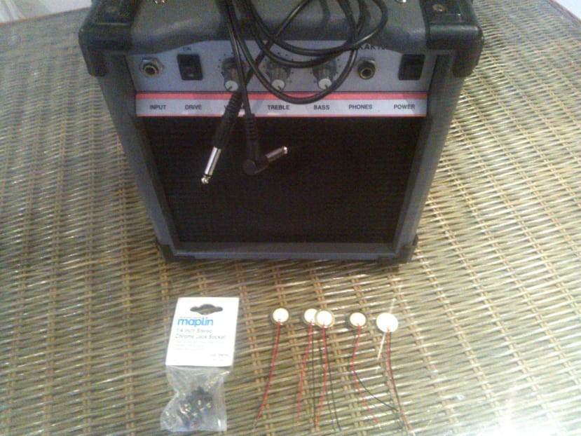
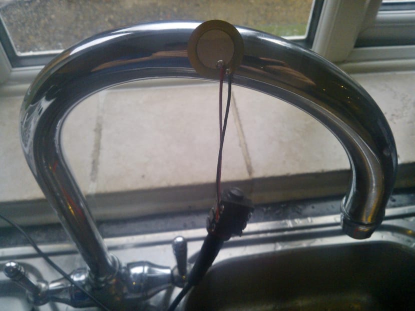
With the Doppler-effect assumed just as infeasible as my time of flight sensor, my approach to frequency-domain flow sensing was intentionally unorthodox at first. I wanted to listen to the acoustic properties of the water running through the pipe to see if there was anything immediately apparent that I could utilise. To do this I used a piezo element attached to a faucet. I then interfaced the element to my guitar amplifier set to a clean tone and zero distortion.
I have a loose understanding of fluid-dynamics, enough to assume by ear, the change in flow profile from laminar to turbulent flow as I turned the tap. However, there was nothing else acoustically that could be easily correlated by ear.
My next approach was to connect the piezo-element to an oscilloscope to determine if I could correlate anything visually using a frequency domain analysis while increasing the flow rate.

I started with the tap a third open to examine the initial frequency-spectrum, as can be seen, it didn’t inspire a lot of confidence given the random scattering of frequency peaks and harmonics with a non-static profile for me to interpret. I figured this was due to the dynamic vortexes apparent in low levels of flow, so I decided to increase the flow to see if there was any improvement.

Nope. As can be seen, the frequency profile does not improve when I open the tap to 50% with an equally random and constantly changing frequency profile.

Finally, when we open the taps, quite literally, and give it 100% flow, we see a significant shift in acoustic profile as it shows what looks to be a turbulent flow profile with much less chaotic noise in the frequency domain as it calms down to almost silence. Unfortunately, this is equally as unhelpful as the signal is now extremely small with a high signal to noise ratio.
In conclusion, we can see that this method wasn’t an ideal solution either and I was running out of ideas at this point…
Amperes Law and Hall Effect Sensor Development
My last idea was a bit on the experimental side but a seemingly simple one to implement. Having seen the experiments online of how you can displace water using an electrically charged rod, made me think that I could use the static electricity in water molecules to my advantage and monitor the current (that’s electrical current) of water flowing in a pipe. Please keep in mind that I am an engineer, not a physicist…
Using Amperes law as the basis for my sensor design theory, a constant magnetic field should be generated around the pipe as water flows. With this assumed, I then attached two hall-effect sensors in opposing directions to give me a differential signal which I could feed into a 16-bit ADC with a pre-gain of 16 for resolving even the smallest of signals. I then tested it with a magnet which worked perfectly.
In accordance with the theme that seems to be developing, I could not get the sensor to detect flow in the pipe. This may be because the induced magnetic field is too small to measure with basic sensors, or my theory is way off and the electric dipoles in water molecules cancel out any resultant electrical current…
A worthwhile experiment but once more, an infeasible one.
Conclusions and Chosen Sensing Method
Having already spent a decent amount of time on my experiments, I needed a sensor solution before I could start the development of the rest of the leak detection system. Having concluded that all the methods I investigated were either infeasible or too costly to further develop, I decided that the non-intrusive sensor requirement for a cost-effective leak detection system is not possible to implement. So I decided to invest in an intrusive sensor as a placeholder for this requirement.
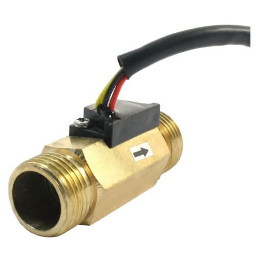
Despite my failures with hall-effect sensors, I could buy a perfectly working magnetic sensor more cost-effectively than I could build one myself. The solid-state nature of the intrusive magnetic sensor means reliability and long life which is what is needed in a failsafe system. With a standard ½ inch thread and non-corrosive brass body, it is perfect for fitting to domestic plumbing systems. This is what the system is currently based around but could be replaced easily at a later development date.
Non-Intrusive Automatic Stopcock Development
In a similar situation to the flow meter, there are lots of easily implemented intrusive electric valves available such as a 12v solenoid, but the challenge requirement stated the use of a non-intrusive automatic stopcock. The real challenge here would be to make it easy and fast to fit while allowing for variations in the different types of stopcock tap-heads and the different rotations needed to turn them off and on again.
I have designed some retro-fit systems in the past, the problem with these systems is always mounting and anchorage, stopcocks are especially difficult due to their cylindrical nature i.e. there are no flat surfaces to clamp something squarely to. My design tries to compensate for this by using a clamp assembly with a hollowed metal plate around the tap tower to hold it in place.
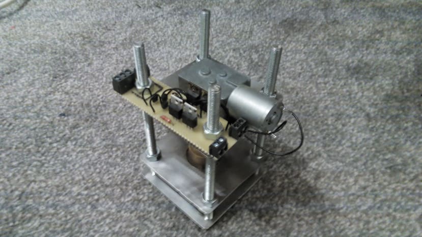
The other difficulty in the challenge was the different number of turns needed to fully actuate different valves, different type of tap heads and the height of each different tap from the pipe. To overcome this, a fully adjustable assembly with plenty of clearance was needed to accommodate the variety in the dimensional requirements. Seen below.
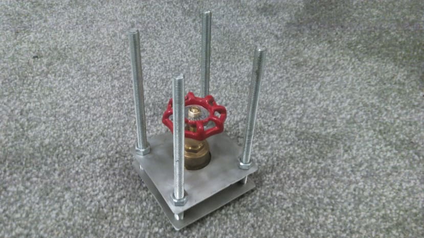
The clamp assembly uses the threaded bar to hold together the plates of the assembly with the tap held in place by the bottom two plates, with the tap head sticking through the hole in the second plate. The threaded bar allows the structure to be adjusted for different types of tap. The third plate is the most involved as it holds the motor, motor driver circuit and flanged motor coupling.
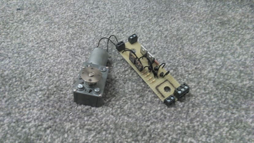
Each tap I experimented with were all very different in the number of turns they need to open/close the valve, I got a range of 90 degrees to 1260 degrees and it is not easy to find a closed loop motor solution that will give you this sort of range and it is extremely hard to design end-switches to non-standard equipment. I deliberated on motor types and control systems for a while and eventually decided that a DC motor would be the best option, that didn’t require programming by the customer or any complicated circuitry that has a higher risk of failing.
I decided to use a current-sensing H-bridge circuit to detect when the tap was reaching the end of its actuation i.e. when the motor started to stall, at which point the circuit would stop the actuation. Using this method makes the system massively flexible for a lot of tap types. Combined with the flanged motor coupling, the assembly can be adjusted to any tap type, height and head using the holes in the flanges to grip each different tap head with easily fitted cable ties.
This method works excellently but due to time limitations I decided to once again to use a placeholder valve in the form of a solenoid, which in my personal opinion would be preferable over a non-intrusive system anyway due to size, ease of actuation, the circuitry required and ironically ease of fitting.
Costing Analysis
Most of my components were sourced from RS and so the project should be easy to recreate from searching their online site or where components were unavailable, from private retailers online.
Main component breakdown for the motherboard
Enclosure (£8.24), Matrix board (£3.44), CANBUS module (£0.99), SD module (£3.78), LCD module (£1.12), RTC (£0.99), Cable glands (£0.75 for two), DC socket (£0.10), Flow sensor (£3.48), Dynamo (£4.12), Solenoid (£2.64), Terminal blocks (£0.58), MCP23S17 (£0.82), Signal transistors (£1.39), 5v linear regulator (£0.16), SiPy development board (£25.99).
Total estimated motherboard cost: £58.59
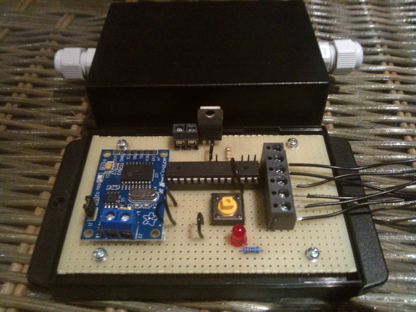
Main component breakdown for each sensor node
Enclosure (£3.31), Matrix board (£1.72), CANBUS module (£0.99), ATMEAG328P-PU (£1.09), Cable glands (£0.75), Terminal blocks (£0.73), Moisture sensors (£1.98).
Total estimated node cost: £10.57
The estimated total cost for my entire system is equal to £79.73 which is in the specified budget but could be a lot lower as a lot of the cost is brought up by the SiPy development board. With the added use of a lot of through-hole component packages in my prototype build, this cost will come down significantly when manufactured professionally on a larger scale.
Final Comments and Conclusions
Overall I am very happy with the results I produced for the DesignSpark LeakKiller Challenge, a lot of hard work and personal investment went into developing it and so I am hoping my design can be of use to Legal & General in their endeavours. It would certainly be rewarding to see my design used in a project this big, it is also worth noting that my system was designed to be scalable to include as many nodes as the user requires, this also means the system can be used to monitor water in much larger insurable establishments such as hotels, which would be exciting to see also.
Given extra time I also wanted to have the motherboard PCB designed for professional manufacture using the DesignSpark PCB software as I am a strong advocate for its use in industry.
I am looking forward to the development of the Pycom hardware and software as it has a lot of potential for IoT applications, given the completion of their APIs and documentation. I would have also liked to investigate the use of SigFox and Wi-Fi networks on my project to link to cloud services as this may be something Legal & General have in mind for future developments.
In conclusion, I hope reading through my entry for the DesignSpark Leak Killer Challenge has been interesting and will have an influence on the final system that will help reduce water damage in the safer and less stressful domestic environments of the future.