Remote Flying Fish Project Part 7: PCB Design (Schematic)
Follow article Dave from DesignSpark
How do you feel about this article? Help us to provide better content for you.
Dave from DesignSpark
Thank you! Your feedback has been received.
Dave from DesignSpark
There was a problem submitting your feedback, please try again later.
Dave from DesignSpark
What do you think of this article?
Over the last chapter, you have already familiarized yourself with the preparatory works of PCB design. And now it is time to start designing a PCB of your own, along with a schematic design for the product circuit.
Schematic — this is a document you might not need during PCB design if you are an expert.
If you are just some normal DIYer like me, please go ahead and start with the schematic design first!
After following the previous chapter, you should have the following prepared:
- DesignSpark PCB
- A list of components to be used
- Datasheets of the components

And here is my list of components, which we also call it BOM(Bill of Materials)
| Components (A.K.A. parts) | Qty | RS Stock No. |
|---|---|---|
| Lithium polymer battery (3.7V, 750mah, 25C) | 1 | N/A |
| Lithium polymer battery USB charging line | 1 | N/A |
| Electrolytic capacitors 470uF 10-25V(e.g 16V for this RS stock no.) | 2 | (708-3620) |
| Electrolytic capacitors 10uF 10-25V | 2 | |
| Tantalum capacitor 10uF 10-35V | 2 | |
| Tantalum capacitor 2.2uF 10-35V | 2 | |
| Tantalum capacitor 1uF 10-35V | 1 | |
| Tantalum capacitor 10nF 10-35V | 3 | |
| Tantalum capacitor 2.2nF 10-35V | 1 | |
| Tantalum capacitor 47pF 10-35V | 1 | |
| 0805 SMD resistor 30kΩ | 1 | |
| 0805 SMD resistor 10kΩ | 1 | |
| 0805 SMD resistor 51kΩ | 1 | |
| 0805 SMD resistor 91mΩ | 1 | |
| Shield inductor 6.8uH | 1 | (770-1198) |
| Schottky diode | 1 | (688-0502) |
| SMD LED | 1 | (710-4821) |
| DC-DC converter IC PAM2421 | 1 | (790-2916) |
| Motor driver IC DRV8833PWP | 2 | (825-3120) |
| HM-10 BLE module | 1 | N/A |
| Arduino Nano 3.0 | 1 | (696-1667) |
| PCB jumpers (female) | several |
(251-8531)
(red) (251-8519) (blue) (251-8553) (green) |
| PCB pin headers | several | (251-8086) |
| PCB socket | several |
180-0452 (1row 15way, the picture is incorrect)
|
For the N/A parts, you might find it easily on Amazon or eBay. And oh, don't forget about the helium tank and fish balloon, they are just so important too.
Rewinding a little bit, how did I get all these components decided? If you still remember, from the first few chapters, we have already had an overview of the final product and understand the functionality that it will have.
Hence, we can confirm the main components, the ICs, and start to work out the required support accessories afterward. For example, the battery is at 3.7V, yet Arduino Nano is working at 5V. So we realize the need for an extra voltage source of 5V, which could be achieved via a DC-DC boost converter.
And for the motion part, we first think about:
- How to create motion? >> Motor
- How to control motor? >> Microcontroller unit (MCU)
- Any bridge in between to connect motors and microcontrollers? >> Motor driver
- How to allow human interactive control over the MCU? >> Bluetooth module + mobile app
That's basically how the skeleton of this product was decided.
DesignSpark PCB
Alright, let's get back to the backbone section. First of all, if you are not already familiar with DesignSpark PCB, you may think that it is difficult to use. But don't worry, there is a decent video tutorial series on YouTube prepared by RS that helps you to familiarize yourself with the use of the software.
Of course, the tutorials do not cover everything, and I will make some complementary notes down below. In addition, it is recommended to start doing while watching the tutorials, as you might not need to learn everything in them.
To start with, take a look at this flow diagram: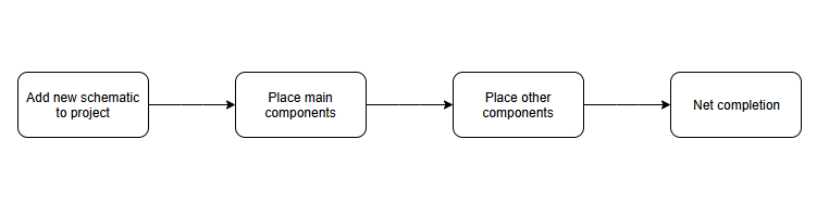
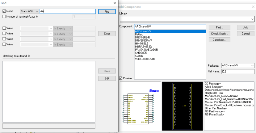
From the screen capture above, you can see the way to search for a component in the Add function (shortcut: F3).
You might wonder how to achieve the second step, as components like Arduino Nano and DRV8833PWP are not in the library.
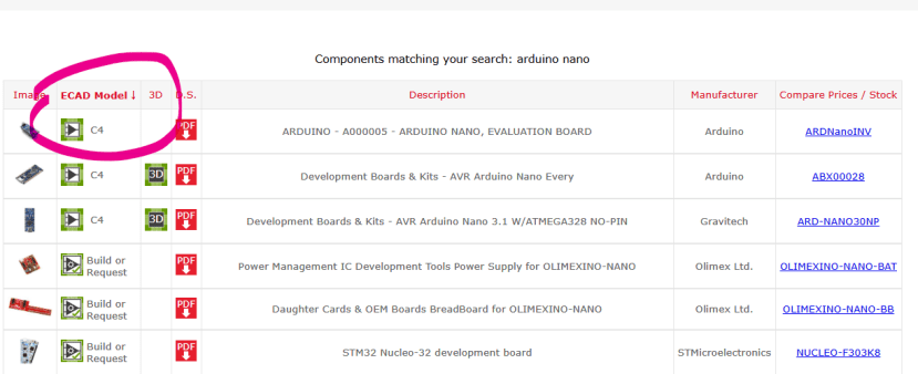
Right, a great discovery. Because they do not exist by default. Referring to the DesignSpark PCB Training | 2 Custom Libraries (video below), you need to add these non-default components yourself. And you should find most of them in the Components Search Engine: https://rs.componentsearchengine.com/
Just log in, search, and download free!
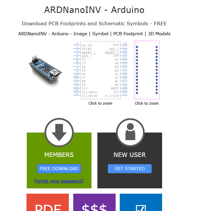
After unzipping the zipped file, you might find many folders in it. When importing into the library, choose the DesignSpark one, and .dsl is the corresponding file extension.
Then, you will find the required components when clicking F3 again. (Remember to choose the correct library.)
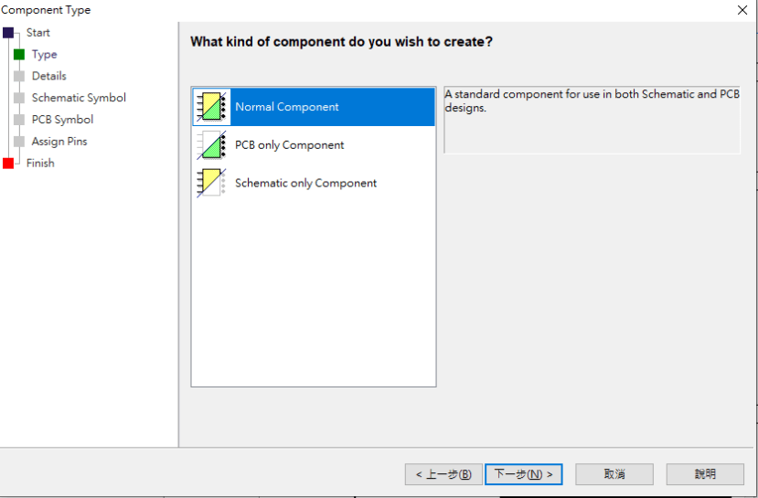
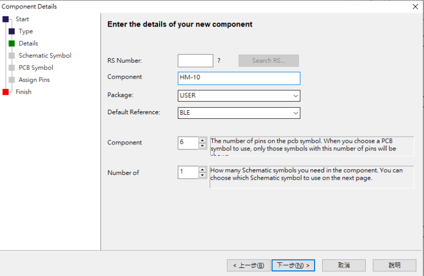
For components you cannot obtain from the search engine, you will need to make your own. Please refer to DesignSpark PCB Training | 3 Creating Components.
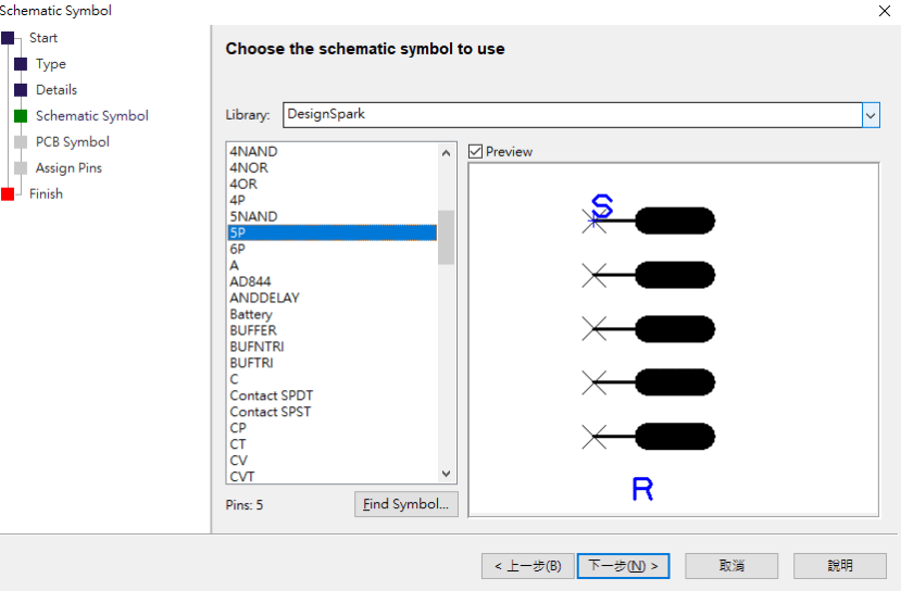
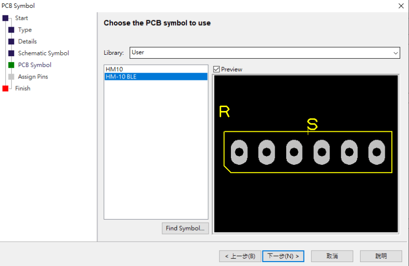
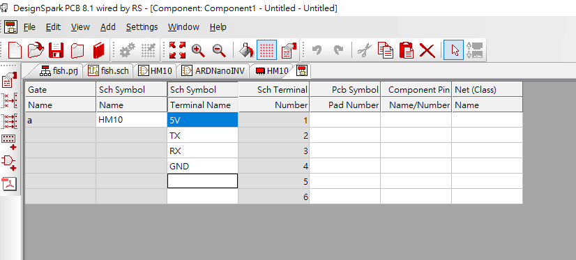
In my schematic, I made the switch and BLE components.
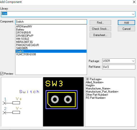
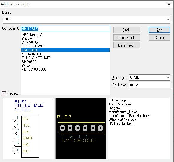
Here are some snapshots from component creation when using Component Wizard.
Furthermore, I usually add several ground (GND) and voltage source (Vcc) into the schematic to avoid chaotic net connections.
Another reminder, don't mix up the tantalum capacitor and Electrolytic capacitor (E-cap) symbol and also mind the +ve terminal of E-cap.
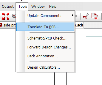
After finishing everything, double-check your design and then do PCB translation.
And? See you next chapter!
Remark: you may wonder why we don't see any motors at this part. Because there is no specific symbol needed for the joints of wire and we will cover this in the next chapter.
Parts in this series
- Remote Flying Fish Project Part 1: Introduction
- Remote Flying Fish Project Part 2: DIY Series - Arduino Testing
- Remote Flying Fish Project Part 3: Motor Testing
- Remote Flying Fish Project Part 4: Bluetooth Testing
- Remote Flying Fish Project Part 5: Motor Testing with Remote XY
- Remote Flying Fish Project Part 6: PCB Design (preparatory)
- Remote Flying Fish Project Part 7: PCB Design (Schematic)
- Remote Flying Fish Project Part 8: PCB Design (PCB Layout)
- Remote Flying Fish Project Part 9: Soldering and Arduino Programming
- Remote Flying Fish Project Part 10: Flutter Introduction
- Remote Flying Fish Project Part 11: Flutter Installation on MacOS
- Remote Flying Fish Project Part 12: Flutter Installation on Windows