Building a Spresense Powered Smart Security Device Part 3: Sensor Processing
Follow article
 Dave from DesignSpark
How do you feel about this article? Help us to provide better content for you.
Dave from DesignSpark
Thank you! Your feedback has been received.
Dave from DesignSpark
There was a problem submitting your feedback, please try again later.
Dave from DesignSpark
What do you think of this article?
In Part 1 we introduced the project and Part 2 covered SDK setup. Having run the “Hello, World” example and verified our tools setup, we’ll now move on to taking a look at one of the more interesting features of the Sony CXD5602 microcontroller, its Sensor Control Unit (SCU). Using this with an attached Bosch BMI160 inertial measurement unit (IMU) sensor and SDK examples.
The SCU is key to the CXD5602’s low power sensing capability and together the multi-core application processor and integrated GNSS sets it apart from other devices in its class.
Hardware setup
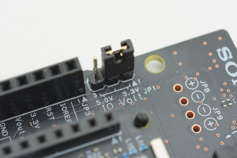
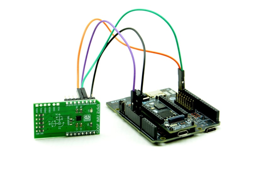
The Spresense Main Board interface voltage is 1.8V, while the Click IMU 2 module (136-0828) we’ll be using for the BMI160 sensor is 3.3V, hence we’ll also use the Spresense Extension Board (178-3377) for level-shifting between the two. This can be configured for either 3.3V or 5V I/O, so we need to make sure that it’s set to the former, as shown above.

The connections between the Extension Board and IMU 2 module are as follows:
- Power GND → GND
- Power 3.3V → 3V3
- JP2 Pin 1 → SCL
- JP2 Pin 2 → SDA
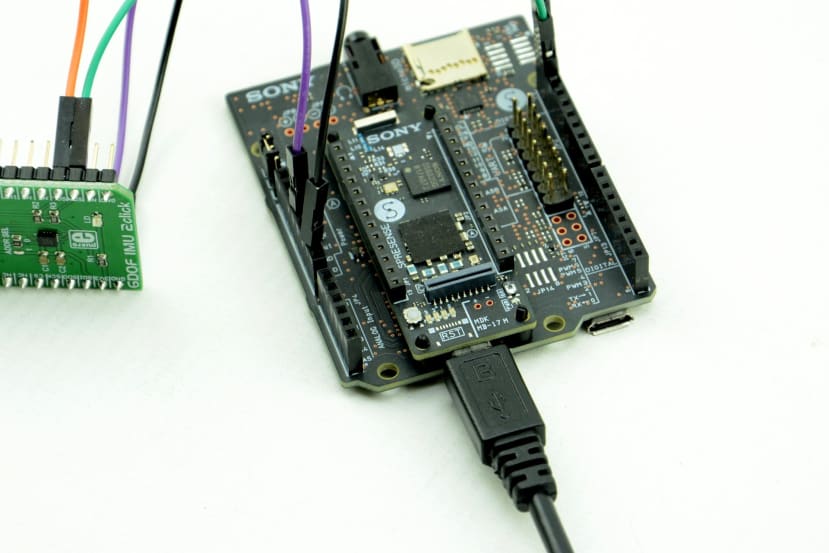
After having set the I/O voltage and wired the IMU 2 module, we can then connect the Spresense Main Board Micro USB port to our development computer.
Sensor Control Unit

The SCU is responsible for reducing the processor load and power consumption of the CXD5602, which it achieves by offloading common sensor processing tasks to dedicated, highly efficient hardware. This is relatively simple to configure using the Spresense SDK and compatible drivers are included for a number of devices, including the Bosch BMI160.
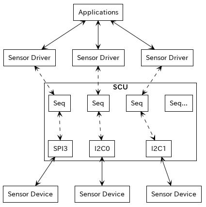
The SCU has one SPI and two I2C buses, plus eight sequencers and two decimators. Applications can configure the SCU to automatically receive sensor data, perform decimation, filtering and event detection — all without involving the main CPU.
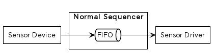
The sequencers provide FIFOs that are configured with a device sampling rate and a watermark, that together will determine how often the SCU driver will signal the application. For example, a sampling rate of 128Hz with a watermark of 128, will cause the SCU to signal every 1 second.
The following devices are currently supported by the SCU:
- BMI160 gyroscope and accelerometer
- AK09912 magnetometer
- KX022 accelerometer
- BM1422GMV magnetometer
Information is also provided for developers who wish to add support for new devices.
Finally, it’s worth noting that SPI and I2C buses controlled by the SCU can be accessed directly, which if done at the same time as using the SCU for device access, would result in bus conflict.
Decimation

Decimation is the process of reducing the sample rate and this is a function of the sequencer. By default, a cascaded integrator–comb (CIC) filter is also applied. In reducing the sensor data sample rate to the Application Processor, we can reduce the load on this and in turn the power consumption. This is configured using SCUIOC_SETDECIMATION and the decimation_s data structure.
struct decimation_s dec;

dec.ratio = 1;
dec.leveladj = SCU_LEVELADJ_X1;
dec.forcethrough = 0;

ret = ioctl(d->fd, SCUIOC_SETDECIMATION, (unsigned long)(uintptr_t)&dec);
Setting the ratio member to 0 would result in no change to the sampling rate and setting it to 1 would half it. The leveladj member can also be set to _2, _4 and _8 in order to amplify the sensor data. If we wanted to disable the CIC filter we would set forcethrough to 1.
We can assign a supported device to the decimator by running make menuconfig from within the sdk directory (see Part 2) and then selecting CXD56xx Configuration > Sensor Control Unit (SCU) > SCU Decimator assignments.

Note that the I2C slave address is set to 0x68 by default and this is what our IMU 2 module configures the BMI160 for. However, if necessary this can be changed in the SDK.
Decimator example
We could use make menuconfig to configure the decimator example, but a much simpler way is to use predefined defconfig by entering:
$ tools/config.py examples/decimatorFollowing which we can build the example, flash it to the Spresense module and then run it by entering “decimator” at the NuttShell prompt.
$ make buildkernel

$ make

$ tools/flash.sh -c /dev/ttyUSB3 nuttx.spk

$ screen /dev/ttyUSB3 115200
As the IMU 2 module is rotated along one axis we see the values output change.
What is happening is that two decimators are set up: a first with the default forcethrough behaviour, which means that it acts as a normal sequencer and without any actual decimation; and a second decimator with a ratio of 1 / 2, which at 32 Hz rate gives 16 samples/second. It’s not possible to see the output of both in the above video, so here’s a capture of 1s output.
Decimator 0:
[  0] xyz =    764, -16384,  -3451
[  1] xyz =    752, -16398,  -3396
[  2] xyz =    740, -16393,  -3411
[  3] xyz =    742, -16395,  -3437
[  4] xyz =    752, -16389,  -3413
[  5] xyz =    747, -16391,  -3436
[  6] xyz =    747, -16387,  -3426
[  7] xyz =    752, -16399,  -3419
[  8] xyz =    754, -16396,  -3427
[  9] xyz =    745, -16388,  -3437
[ 10] xyz =    747, -16378,  -3419
[ 11] xyz =    764, -16379,  -3424
[ 12] xyz =    753, -16388,  -3433
[ 13] xyz =    749, -16397,  -3428
[ 14] xyz =    755, -16404,  -3417
[ 15] xyz =    760, -16409,  -3436
[ 16] xyz =    755, -16392,  -3458
[ 17] xyz =    749, -16380,  -3418
[ 18] xyz =    754, -16385,  -3426
[ 19] xyz =    759, -16388,  -3456
[ 20] xyz =    750, -16378,  -3448
[ 21] xyz =    745, -16378,  -3417
[ 22] xyz =    759, -16373,  -3416
[ 23] xyz =    766, -16382,  -3434
[ 24] xyz =    754, -16403,  -3426
[ 25] xyz =    751, -16395,  -3436
[ 26] xyz =    741, -16381,  -3450
[ 27] xyz =    754, -16392,  -3456
[ 28] xyz =    757, -16403,  -3432
[ 29] xyz =    740, -16405,  -3436
[ 30] xyz =    749, -16390,  -3435
[ 31] xyz =    745, -16374,  -3428

Decimator 1:
[  0] xyz =    749, -16393,  -3434
[  1] xyz =    752, -16394,  -3437
[  2] xyz =    750, -16389,  -3430
[  3] xyz =    748, -16387,  -3429
[  4] xyz =    757, -16392,  -3436
[  5] xyz =    758, -16393,  -3434
[  6] xyz =    748, -16397,  -3431
[  7] xyz =    748, -16394,  -3431
[  8] xyz =    751, -16388,  -3433
[  9] xyz =    751, -16392,  -3437
[ 10] xyz =    750, -16394,  -3439
[ 11] xyz =    749, -16395,  -3431
[ 12] xyz =    755, -16392,  -3430
[ 13] xyz =    754, -16394,  -3439
[ 14] xyz =    747, -16393,  -3441
[ 15] xyz =    745, -16383,  -3436
As we can see, decimator 1 outputs half the number of samples.
IIR filter

An infinite impulse response (IIR) filter is a type of digital filter that efficiently achieves a given transfer function. For example, this might be that of classic analogue filters, such as Chebyshev and Butterworth filters. The SCU can use two IIR filters and these can be set to any combination of positions with respect to FIFO and event detector, as shown above in paths labelled A, F and E.
IIR filters are configured using coefficients. The calculation and testing of these can be facilitated using tools such as Matlab and GNU Octave, along with dedicated filter design tools. Each coefficient is a 34-bit fixed-point number that is set using the iir_coeff_s data structure.
Event detector

The event detector is a monitoring feature that counts input sensor data as high or low compared to a configured threshold. If the counted value reaches the threshold, the event detector sends an interrupt which the application receives as a signal with a timestamp. It is configured with the scuev_notify_s data structure, which has rise and fall members, each of which has a threshold, count0 and count1 member.
The SCU notifies the application when the input data count reaches count0 + count1. The event detector requires IIR filter output and this must be configured first.
Let’s take a look at the event detector in use.
Tilt example
static const struct scuev_notify_s g_notify =
{
  .signo = EVENT_SIGNAL,

  /* If you want to see about actual data, please change SCU_EV_NOTOUT to
   * SCU_EV_OUTALWAYS */

  .ctrl = SCU_EV_RISE_EN | SCU_EV_NOTOUT,
  .rise = {
    .threshold = 10000,
    .count0 = 5,
    .count1 = 10,
    .delaysamples = 0,
  },
  .fall = {
    .threshold = 10000,
    .count0 = 5,
    .count1 = 10,
    .delaysamples = 0,
  },
  .arg = &g_evarg,
};
Tilt example SCU event detector configuration.
The SDK tilt example configures both IIR filters in the A position, where they apply to both the FIFO and event detector. However, it sets the coefficients for these to equal multiplication and so filtering is not actually performed. The event detector is then set up as shown above.
We can configure the example with:
$ tools/config.py examples/tiltFollowing which we can build the example, flash it to the Spresense and run it by entering “tilt” at the NuttShell prompt.
$ make buildkernel

$ make

$ tools/flash.sh -c /dev/ttyUSB3 nuttx.spk

$ screen /dev/ttyUSB3 115200
As the IMU module is tilted and the threshold is reached, we see the output on the console.
Summing up and next
The SCU provides powerful capabilities whereby sensor data can be autonomously sampled, amplified and filtered, and an application only notified when a threshold is triggered. As such it has the potential to significantly reduce the load on the main CPU and in turn power consumption while simplifying development as applications are left to focus on the main task at hand.
In the next post, we’ll take a look at the GNSS subsystem and flash storage, which together with the capabilities covered in this post, will give us the ingredients for our security device use case.