Building a Cosmic Ray Detector Part 3: Completion and Testing
Follow article
 Dave from DesignSpark
How do you feel about this article? Help us to provide better content for you.
Dave from DesignSpark
Thank you! Your feedback has been received.
Dave from DesignSpark
There was a problem submitting your feedback, please try again later.
Dave from DesignSpark
What do you think of this article?
Final assembly of the CosmicWatch detector and Raspberry Pi configuration.
CosmicWatch is a project from MIT in the US and Poland’s National Center for Nuclear Research, that enables anyone with basic electronic skills to build a low-cost desktop detector for the muon particles which are created when cosmic rays collide with the earth’s atmosphere.
In Part 1 in this series we took a look at primary vs. secondary cosmic rays, how we would go about detecting the latter, and introduced CosmicWatch. Part 2 went on to cover the theory of operation in a little more detail, before going on to cover assembling and testing of the main PCB, with some thoughts also on reproducible design. This post takes a look at putting together the SiPM detector assembly and configuration of an attached Raspberry Pi host running the CosmicWatch software.
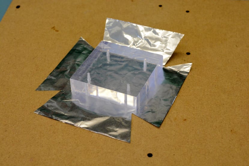
Detector assembly
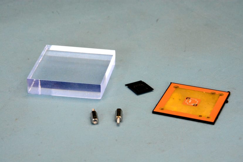
Above we can see the main components for the detector assembly. On the left is the scintillator, in the middle we have the SiPM in protective packaging, and on the right is the detector PCB.
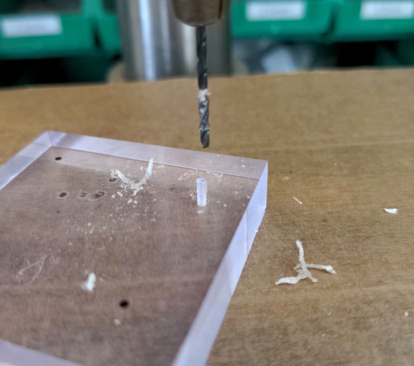
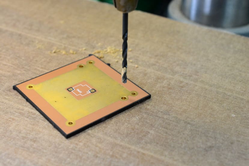
First, the scintillator needs to be drilled, so that it can be secured to the PCB. The instructions suggested using a US sized self-tapping screw, but we decided to go with M2 fixings and to tap the scintillator, hence 1.6mm holes were drilled in preparation.
The instructions cautioned that this should be done with a very low drill speed and to use “peck drilling”. The importance of which cannot be overstated and probably 1-2mm depth each time is advisable. You can see above where the drill bit has gummed up with melted plastic as we were a little too eager, which also results in a wider hole. It helps too if you make sure to clear away the waste material as the drill bit is retracted each time, so as to avoid melting this on the next peck. A small paintbrush can be used for this and to clear any material from the drill bit.
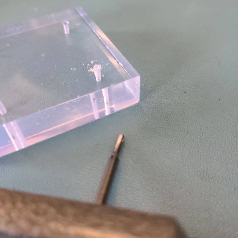
Next, the holes were tapped to an M2 thread (275-9136) .
Note that the six holes in the detector assembly PCB had to be drilled out to 2mm also, along with the two holes in the main PCB where hex spacers are used to affix this.
Next, we checked that the scintillator and PCB could be assembled together. M2 8mm screws (914-1762) were used to secure the two parts.
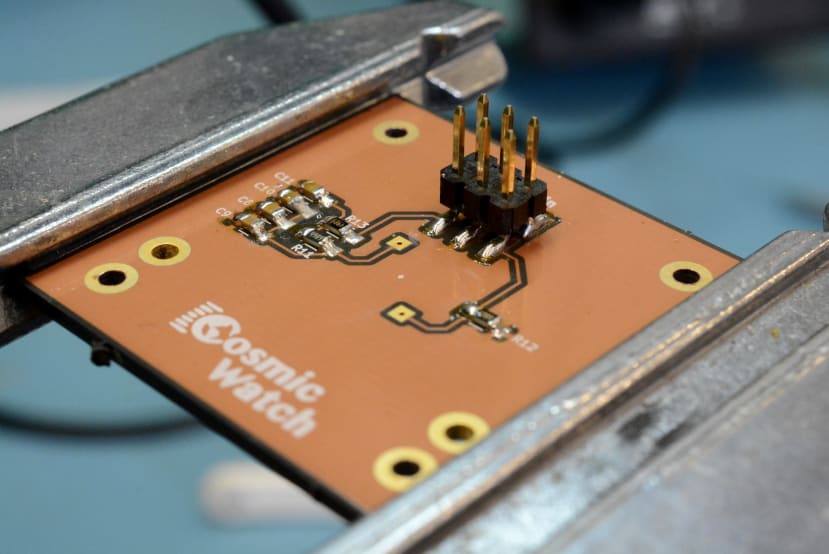
Following which the board was assembled and resistors and capacitors were fitted first. However, it would have made more sense to fit the SiPM first and these after — more on this shortly.
The SiPM datasheet shows how to identify pin 1 so that the device can be oriented correctly. However, this is not easy with the naked eye, some form of magnification is highly recommended and we used a microscope.
A small amount of solder was applied to the two pads for the SiPM and this was placed on top, then heated with a hot air gun. However, it would likely have been better to apply a small amount of solder paste to each pad and then use a hot plate and/or hot air gun. Obviously doing this first and then soldering the resistors and caps on the other side. In any case, it appeared to have worked.
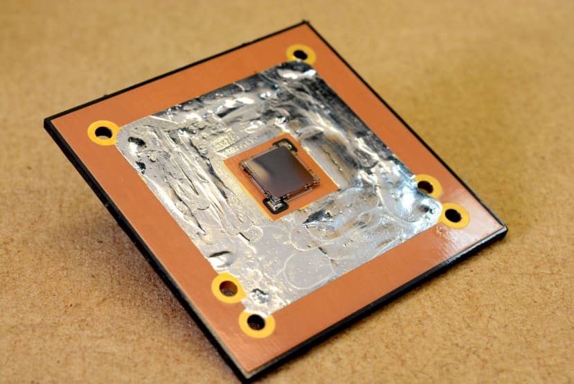
The instructions show a detector PCB that has a large silvered ground plane and notes how this helps to reflect light from the scintillator. Presumably, the PCB has a HASL finish and since ours was ENIG and thus duller, we decided to cover it in solder to increase the reflectivity.
Next, the scintillator was wrapped in foil, so as to further reflect light. This was quite fiddly.
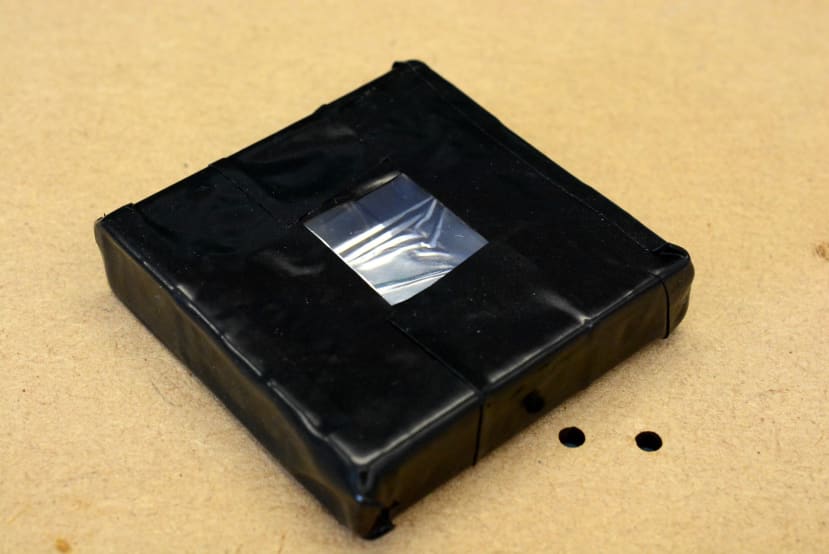
The scintillator was then wrapped in tape to block external light sources. It was decided that a high-quality electrical insulation tape should be used for this and 3M Scotch 88 black PCV tape (909-4521) was selected. This would appear to have been a good choice as it is both very flexible and particularly tacky, hence it conforms and adheres well.
10mm M2 male-female hex standoffs (184-2591) were used to secure the detector assembly to the main PCB, with M2 6mm screws (914-1753) through the former. The optical coupling gel was now applied to the SiPM.
Following which the detector was now wrapped in more tape to keep light out.
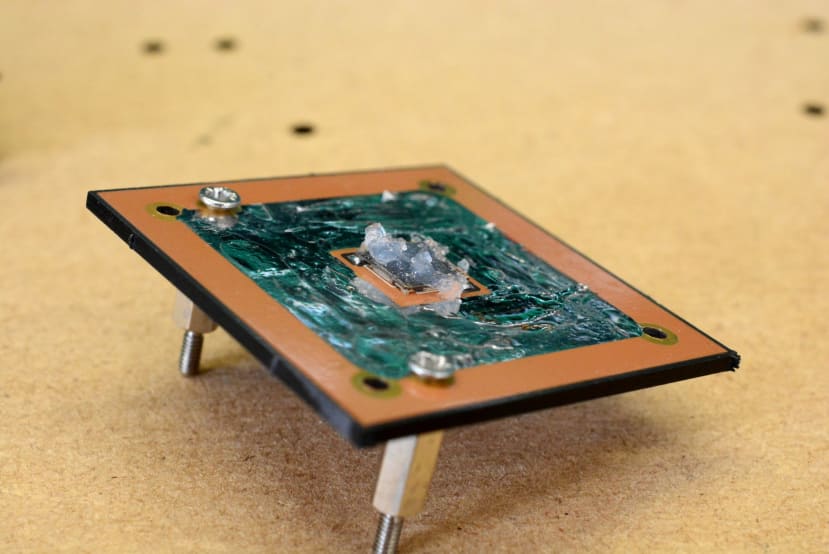
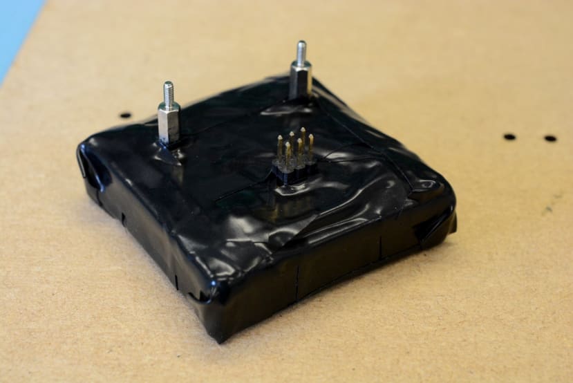
Final assembly
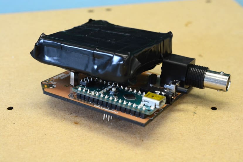
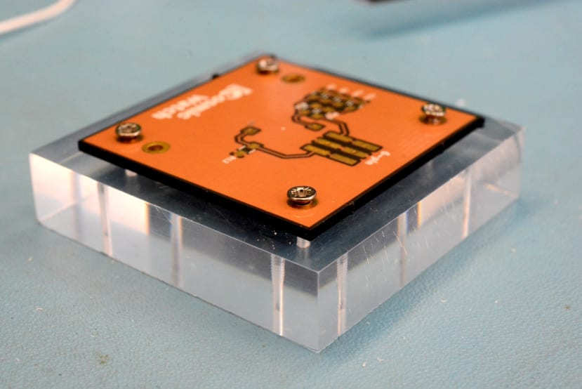
Above we can see the detector affixed to the mainboard. The standoffs are perhaps a touch on the short side, but washers can be used to raise the height a little, as the M2 studs which protrude through the main PCB are sufficiently long. Note how the ISP header pins had to be clipped on the Arduino Nano, as noted previously since we’re using an official board that comes with this fitted.
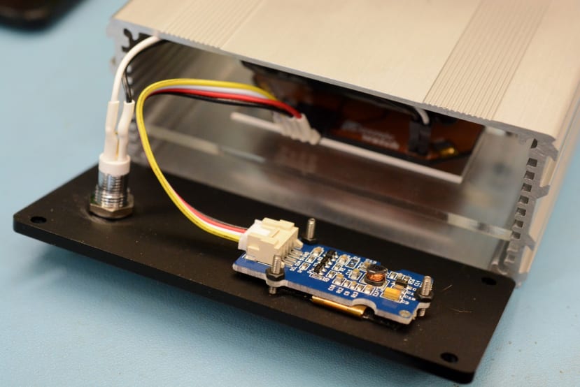
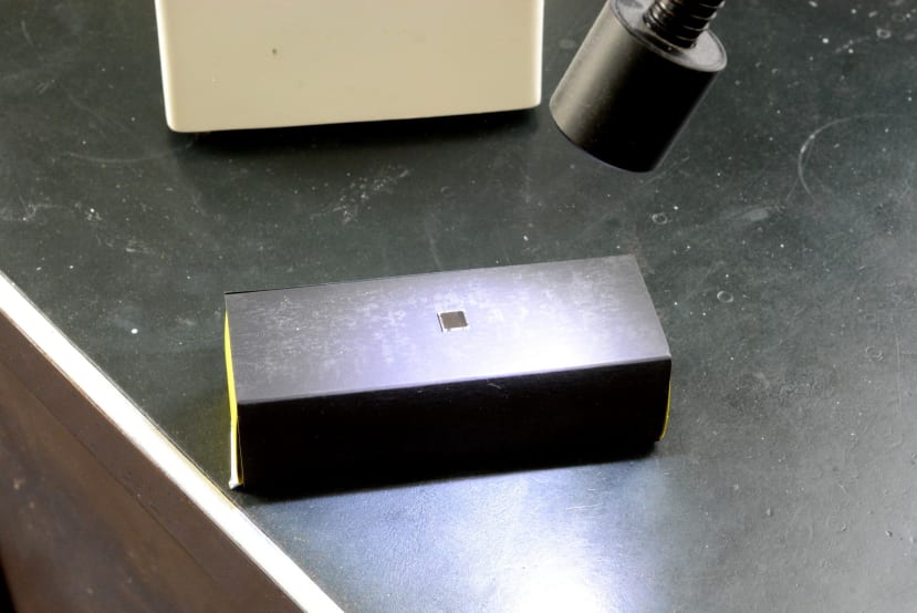
Custom front and rear enclosure panels were laser cut from a 3mm acrylic sheet, using the drawings provided for the slightly smaller case as a starting point. Note that the MicroSD card PCB was not fitted, as we did not succeed in sourcing a card socket with an appropriate footprint. However, this is of little concern as we plan to use the detector with a computer connected and don’t need to do local logging. In addition to this, you cannot have both the OLED screen and MicroSD configured at the same time, so this really isn’t much of a loss.
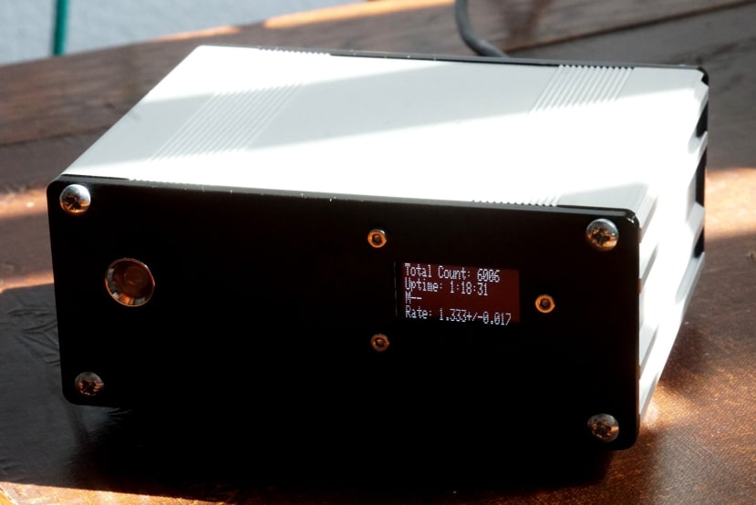
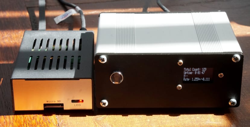
Stand-alone testing
Here we can see the CosmicWatch with power applied and the count rate is a touch higher than expected. As is suggested the detector assembly was re-checked for light leaks and certainly appears to be good in this respect. In addition to this, operating the detector outside of the enclosure makes no discernable difference to the rate measured, whereas one would have expected this to increase if ambient light leakage was a problem.
It is possible that the rate shown is in fact correct and reflects a combination of muons and “radiogenic backgrounds”. A GitHub issue notes that a rate of at least up to 2.5Hz has been seen in use, with roughly 0.4Hz of which coming from cosmic ray muons.
One way to eliminate backgrounds would be to build a second CosmicWatch and cable the two together to operate them in coincidence mode, whereby the second detector would only record an event if the first also registers one within a 30us window.
Finally, there is also a SIGNAL_THRESHOLD variable in the Arduino code, which can be increased. This might be done if a larger scintillator was used or perhaps a material with higher output. However, it seems probable that radiogenic background radiation is the cause here.
Raspberry Pi configuration
A Python script is provided that allows data to be recorded directly via an attached computer, copying of data files from the SD card to computer, and connection to a server. This script could be run on a laptop or desktop, but a Raspberry Pi also makes for a convenient host.
To install the software on a Pi we needed to:
$ sudo apt install git python-serial python-numpy python-tornado

$ git clone

$ cd CosmicWatch-Desktop-Muon-Detector-v2/Recording_Data

$ python import_data.py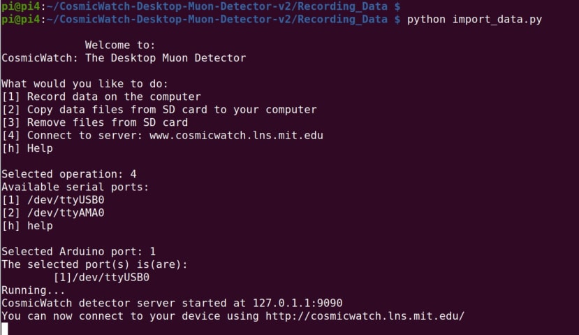
Following which we were presented with the available options and to connect to the website enter 4, followed by 1 to select the appropriate serial port.

If we open the website URL in a browser we will need to first modify the contents of the address field at the top of the page, so that this has the IP for the Raspberry Pi, since it assumes by default that the CosmicWatch will be plugged into the same computer as the browser is being run on. We can then select the button to start.
At this point, we now have a live dashboard with plenty of informative metrics.
Final thoughts
It’s great that it’s now become possible for an enthusiast or school to construct equipment such as this, which not that long ago would have been far more expensive to build and even more so to buy as off-the-shelf equipment. And of course, it is very cool indeed to have a small DIY desktop device that is capable of detecting elementary subatomic particles. With thanks to the team behind CosmicWatch and for making the design freely available for anyone to build.