An access control system with speaker verification
Follow article
 Dave from DesignSpark
How do you feel about this article? Help us to provide better content for you.
Dave from DesignSpark
Thank you! Your feedback has been received.
Dave from DesignSpark
There was a problem submitting your feedback, please try again later.
Dave from DesignSpark
What do you think of this article?
Two-factor authentication with a Riverdi IoT Display module and EasyVR 3 Plus voice recognition system.
Nowadays, we're used to the convenience of using devices with simple voice commands. Thanks to such projects as Google Assistant or Alexa, a virtual assistant will not only allow you to remotely turn on the lighting, but also get information about the current weather, or order a pizza.
This trend does not go unnoticed by manufacturers of consumer electronics who integrate voice control systems in their modules. The implementation of full-fledged assistants in the product – such as Google Assistant, Siri or Alexa – requires the device to run fully functional Android or iOS systems, which forces designers to provide the device with adequate computing power and drastically increases product development time in the hardware area as well as programming.
Two-factor authentication with speaker verification
We wanted to offer the same kind of convenience to digital security. That is why we have created a demo that teaches you how to implement two-factor authentication to Riverdi displays, with the second factor being speaker verification, thanks to innovative technology from Sensory. This is the first project of this kind.
In this article, using the Riverdi IoT display intelligent module, the dedicated Zerynth programming environment (enabling convenient application creation using Python) and the extensive Fortebit EasyVR 3 Plus voice recognition module, we will create a room access control system using two-factor authentication – by entering a PIN code and speaking an individual access password. The interaction with the user system will be carried out using a graphical user interface presented on the 5-inch graphic display of the Riverdi IoT display module and through audio messages generated by the EasyVR 3 Plus module.
Block diagram of the implemented project
Before we start writing the first line of code, let’s analyze the application’s block diagram.
When it comes to simple graphical interfaces, it is worth taking the time to make a clear and functional description on each screen (like we did in Figure 1. below).
- Riverdi Logo – the first screen shows the Riverdi’s logo and confirms that the display initialization is complete.
- Riverdi Screensaver – the screensaver shows when the device is idle, displaying a simple graphic that continuously changes its position. Thanks to the Fortebit EasyVR module, it is enough to pronounce the trigger-word “Hello device” to wake up the display. The trigger command uses the Speaker Independent (SI) technology, as opposed to the Speaker Verification (SV) technology that the voice password uses.
- Pin Pad – next, the user needs to enter a PIN code (the corresponding message will also be played as an audio message). If the PIN code is entered incorrectly, the user will be asked to enter the code again. In the case of inactivity, the application will switch to the default screen saver display mode. Entering the correct PIN code takes the user to the next stage of authorization.
- Enter The Voice Password – the user needs to say an individual password (voice recognition in the SD – Speaker Dependent option). Correct termination of the password assigned to a given PIN code and the user is confirmed by displaying the Access Granted screen and turning on the relay controlling the electromagnetic lock for a period of 5 seconds. After the time has expired, the door is locked again and the user interface returns to the screen saver display stage.
Two-factor authentication:

Figure 1. Block diagram of the implemented access module
Selected hardware solution
In the previous section, we were able to define the operation module of the implemented access module quite well. Looking at the design from the point of selection of equipment for its implementation, we can quite precisely define the requirements for the equipment layer:
- EasyVR module for implementing speech recognition algorithms and generating voice messages,
- an integrated module consisting of a microcontroller and a high-quality display with a screen diameter of 5 inches,
- the ability to easily expand the equipment without the need for independent solder connections (the optimal choice will be the availability of the microBUS connector, which was equipped with the EasyVR module),
- optional support of selected equipment in frameworks that provide the ability to conveniently create code in high-level languages (e.g. Python).
Gathering all the requirements necessary for the implementation of the project, i.e. a good-quality display with a capacitive touch panel, the availability of microBUS connectors and cooperation with the Zerynth programming environment – which will allow us to prepare applications directly in Python – quite quickly directs us to the Riverdi IoT Display module – integrated LCD display system (5-inch diagonal and 800x480 screen resolution), Bridgetek BT81x graphics controller and the well-known ESP32 microprocessor. All intelligent IoT displays provided by Riverdi have a pre-installed Zerynth Studio license, so we can start working with the module right after removing it from the packaging. To sum up and characterize the hardware choices made briefly:
Riverdi IoT Display – this module will be the heart of our project. Thanks to the 5-inch capacitive display with a resolution of 800x480, and the graphics controller BT815 we will be able to easily and quickly prepare a graphical user interface, without the need to create all the components of the interface by yourself. In the final solution, this module will be mounted in the form of an aesthetic wall module – see Figure 2.


Figure 2. Riverdi IoT Display module
EasyVR 3 Plus – this module will be responsible for the implementation of tasks related to the recognition and analysis of voice and playback of previously recorded audio samples, performing a complementary role to the graphical user interface presented on the display. An important functionality of the EasyVR module is the separation of the commands "Speaker Independent" (SI), "Speaker Dependent" (SD) and “Speaker Verification” (SV). By default, the module has preloaded basic SI commands that are typical for automation systems, as well as generic commands that define directions, numbers or action commands. The module also has the ability to upload personalized SI instructions using the dedicated QT2SI Lite Software.

Figure 3. EasyVR 3 (Plus) voice recognition module
Relay click – MikroElektronika’s MikroBUS board
(820-9858)
equipped with two relay outputs together with status signaling via LEDs located on the module. In the implemented project, the relay output will be responsible for controlling the operation of the electromagnetic lock.
What about the installation of the entire system? Nothing easier!
According to the markings on the PCB, plug the Relay click and EasyVR modules into the microBUS sockets located on the Riverdi IoT Display module – connect the prepared set using a micro-USB cable to your computer and it's ready! We can now start preparing the software.
Development environment
Zerynth – a programming environment that allows you to quickly, easily and conveniently create Python software (with the option of implementing functions in C) on the most popular embedded systems. A large number of supported hardware platforms (including Riverdi IoT Display inclusive) and ready-made software libraries (including a library that facilitates the operation of the EasyVR module) will significantly accelerate and facilitate the preparation stage of the target access module software.

Figure 5. Integrated code editor – Zerynth Studio
EasyVR Commander – for the purposes of managing the EasyVR module (including creating your own voice commands, uploading audio samples or configuring the module), the developers have prepared a dedicated EasyVR Commander application with a simple and intuitive graphic interface – see Figure 6.

Figure 6. The main EasyVR Commander window
EasyVR module configuration
We start the configuration of the equipment with the Fortebit EasyVR 3 module. To do this, connect the module with the computer using the included USB-UART signal converter. After launching the EasyVR Commander application, select the serial port and click the Connect button. The application will automatically read the current command groups programmed in the module and display them as a list – see Figure 7.

Figure 7. List of command groups read from the EasyVR module
According to the adopted concept, user passwords will be placed under a special “Password” group (marked with number 16), which allows you to store up to five passwords, saved and recognized according to Speaker Verification (SV) technology (as opposed to Speaker Dependent technology, passwords saved using SV are more sensitive to correct elimination of background noise and distance from the microphone). To wake up the system from the screen saver display stage, we will use commands from the Grammar group, in which the user can place a set of own SI commands created using QuickT2SI software (this module can be additionally installed with the EasyVR 3 Commander software). The module manufacturer has prepared a short instructional video showing the typical operation of uploading command sets to the Grammar section:
An alternative solution to the process of creating your own Grammars set is to use ready-made Grammars sets available on the EasyVR module manufacturer's website.

Figure 8. A set of audio samples defined within Group 1
The exact configuration of speech recognition process parameters as well as parameters related to e.g. the location of the microphone relative to the user is available in the Recognition Settings tab – Figure 9 below.

Figure 9. Recognition Settings window
Zerynth – environment installation and device virtualization
The completeness of the chosen hardware solution allows us to move quickly to issues related directly to the software. We start this process by downloading the integrated and cross-platform (made available for Windows, Linux, and macOS) Zerynth Studio development environment. The entire installation process is standard in the selected operating system. At the first start of the installer, the user will be asked to accept the license agreement and choose the installation method (online or offline installation – provided that the user has previously downloaded library repositories). The last step in the installation process is choosing the software version (when you created the article, the last available version is r2.3.0). After the installation process is completed, we connect the Riverdi IoT Display to the computer using a micro-USB cable. In the next step, let's create a new virtual machine. To do this, select the device from the 'Device info' drop-down menu, click the 'Create' button to create a new virtual machine, then the 'Virtualize' button to virtualise your device – see Figure 10 below.

Figure 10. Registration and virtualization of the new Riverdi IoT Display device in the Zerynth environment
After the device virtualization process is finished, we are ready to start the programming stage!
Riverdi IoT Display module software
To increase the readability of the created code, divide its structure into two separate files: main.py – containing the code implementing the main functions of the program, and gui.py in which the functions responsible for the user interface will be placed. We start editing the code by importing in the main.py file libraries to support the BT81x graphics controller and EasyVR speech recognition module:
from riverdi.displays.bt81x import ctp50
from bridgetek.bt81x import bt81x
from fortebit.easyvr import easyvr
In the next step, we proceed to the configuration of serial ports – SERIAL1 is responsible for the communication with the EasyVR module:
streams.serial()
ser = streams.serial(SERIAL1, baud=9600, set_default=False)
evr = easyvr.EasyVR(ser)
For the needs of the start screen and screen saver, we attach previously prepared graphics in the PNG format to the graphic resources of our project:
new_resource('images/gui_riverdi_logo.png')
new_resource('images/screensaver.png')
For the needs of the project – using EasyVR 3 Commander – the SoundTable section contains a set of audio samples in which voice messages for the user are placed, e.g. "access denied", "please say your password", etc. To not use the order numbers of individual audio samples, we assign individual recordings to clearly defined variables:
SND_Access_denied=1
SND_Access_granted=2
SND_Hello=3
SND_Please_repeat=4
SND_Please_say_your_password=5
SND_Hello_give_command=6
SND_Please_say_name=7
SND_Pwd_activated=8
Next, the main.py file links are initializing the BT81x controller connected to the SPI bus:
bt81x.init(SPI0, D4, D33, D34)
The final stage of initialization is adjusting the EasyVR module configuration to the needs of our application. At the initialization stage, we configure parameters such as accuracy and, therefore, command recognition speed, speaker language or Timeout value:
evr.setLevel(2)
evr.setLanguage(evr.ENGLISH)
evr.setKnob(evr.STRICTER)
evr.setCommandLatency(evr.MODE_FAST)
evr.setTimeout(6)
Thus, we completed the initialization process. In the next lines of code, create a simple loop that will perform the detection process of the EasyVR module:
while not evr.detect():
print("EasyVR not detected!")
print("EasyVR detected")
id = evr.getID()
print("EasyVR version id: %s" % id)
After successful detection of the EasyVR module, let's check the contents of its module memory by typing in the terminal
mask = evr.getGroupMask()
if mask != None:
for group in range(evr.PASSWORD + 1): #all groups: 0 to 16
if mask & 0x01 != 0:
count = evr.getCommandCount(group)
if group == evr.TRIGGER:
print("Trigger: "+ str(count))
elif group == evr.PASSWORD:
print("Password: " + str(count))
else:
print("Group " + str(group) + ": " + str(count))
for idx in range(count):
(name, train) = evr.dumpCommand(group, idx)
if not evr.isConflict():
print("%d %s Trained %d times, OK" % (idx,name,train))
else:
confl = evr.getWord()
if confl >= 0:
print("%d %s Trained %d times, Similar to Word %d" % (idx,name,train,confl))
else:
confl = evr.getCommand()
print("%d %s Trained %d times, Similar to Command %d" % (idx,name,train,confl))
mask >>= 1
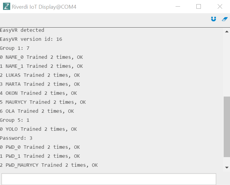
Figure 11. Displaying the EasyVR module memory content
We are ready to draw our first user interface window! Before you proceed, it's worth getting acquainted with the Zerynth API documentation for the BT81x controller:
To speed up our work, let's create a function that will load the image into the internal RAM memory of the BT81x controller (from address 0 in the RAM_G memory area):
def loadImage(image):
bt81x.load_image(0, 0, image)
Where the subsequent arguments refer to the address in RAM, additional options and the variable representing the loaded image, respectively.
The image placed in memory will be displayed using the showLogo () function located in the gui.py file. We start this function by cleaning the screen:
def showLogo():
bt81x.dl_start()
bt81x.clear_color(rgb=(0xff, 0xff, 0xff))
bt81x.clear(1, 1, 1)
And then create a Bitmap class object and draw the image on the display using the draw () method, giving the image coordinates as an argument:
image = bt81x.Bitmap(1, 0, (bt81x.ARGB4, 642 * 2), (bt81x.BILINEAR, bt81x.BORDER, bt81x.BORDER, 642, 144))
image.prepare_draw()
image.draw(((bt81x.display_conf.width - 642)//2, (bt81x.display_conf.height - 144)//2), vertex_fmt=0)
Finally, finish the frame, replace the current Display List:
bt81x.display()
bt81x.swap_and_empty()
The main.py file puts the gui.loadImage () and gui.showLogo () functions:
gui.loadImage('gui_riverdi_logo.png')
gui.showLogo()
sleep(3000)
The obtained effect is shown in Figure 12.

Figure 12. The effect of calling the loadImage () and showLogo () methods
The variable screenLayout, which indicates which element of the interface is currently displayed, will be responsible for making the transition between subsequent screens of the user interface. The screen selection will be implemented in the main program loop:
if screenLayout == 1:
gui.loadImage("screensaver.png")
#screensaver logo parameters
screensaver_logo_width = 300
screensaver_logo_height = 75
evr.recognizeWord(4)
cnt = 0
It's time to realize the functionality related to the screen saver display and waiting for the phrase "Hello Device" (by enabling the recognition of Grammar 4 group commands):
while screenLayout == 1:
if evr.hasFinished():
if evr.getWord() == 0:
screenLayout = 2
break
evr.recognizeWord(4)
else:
cnt += 1
sleep(100)
if (cnt == 20):
x = random(1,bt81x.display_conf.width - screensaver_logo_width)
y = random(1,bt81x.display_conf.height - screensaver_logo_height)
gui.showScreensaver(x,y)
cnt = 0
In the main while loop for the condition screenLayout = 1, we check cyclically the correct recognition of the phrase "Hello Device" and refresh the content of the screen saver. When the return is recognized, the value of the screenLayout variable is changed and the while () loop is broken. The body of showScreensaver (x, y) is a modified version of the method showImage ():
def showScreensaver(x,y):
bt81x.dl_start()
bt81x.clear_color(rgb=(0x00, 0x00, 0x00))
bt81x.clear(1, 1, 1)
image = bt81x.Bitmap(1, 0, (bt81x.ARGB4, (300) * 2), (bt81x.BILINEAR, bt81x.BORDER, bt81x.BORDER, 300, 75))
image.prepare_draw()
image.draw((x, y), vertex_fmt=0)
bt81x.display()
bt81x.swap_and_empty()

Figure 13. Screen saver window
It's time to go to the first form of user verification – entering the PIN using the on-screen keyboard. A fragment of the main.py file responsible for displaying this part of the user interface is shown below:
counter = 0
while (screenLayout == 2):
if (wait == True):
wait = False
sleep(2000)
gui.pinScreen(pin)
if counter == 500:
screenLayout = 1
sleep(10)
counter += 1
pin=""
The task of gui.pinScreen () as the display of the numeric screen keyboard. This operation can be easily accomplished by using the bt81x.add_keys () method:
bt81x.track(430, 50, 350, 70, 0)
bt81x.add_keys(430, 50, 350, 70, 30, 0, "123")
bt81x.add_keys(430, 130, 350, 70, 30, 0, "456")
bt81x.add_keys(430, 210, 350, 70, 30, 0, "789")
bt81x.add_keys(430, 290, 350, 70, 30, 0, ".0C")
The numeric keyboard is supplemented with the "Connect" button, and then we assign to it the value of the TAG field, which will allow us to operate the buttons at a later stage of the program:
btn = bt81x.Button(430, 370, 350, 70, 30, 0, "Connect")
bt81x.tag(1)
bt81x.add_button(btn)

Figure 14. User interface with a numeric keypad
Button support requires from us the function of callback event handling from the touch panel defined in the main.py file. In this case, the pressed () function will be responsible for all events:
bt81x.touch_loop(((-1, pressed), ))
Body function pressed ():
def pressed(tag, tracked, tp):
global screenLayout
global pin
global wait
global counter
global user2
#if we are in pinscreen
if (screenLayout == 2):
counter = 0
user2 = False
if ((tag != 67) and (tag !=1)):
if (len(pin) >= 4):
return
pin = pin + str(chr(tag))
elif ((tag == 67) and (len(pin) > 0)):
pin = pin[:-1]
elif ((tag == 1) and ((pin == valid_pin) or (pin == valid_pin2))):
if pin == valid_pin2:
user2 = True
screenLayout = 4
elif (len(pin) > 0):
wait = True
pin = ""
gui.showMessage("Access Denied")
#go to screensaver
evr.playSound(SND_Access_denied, evr.VOL_FULL)
Each time you touch the screen and call the pressed () function, the counter variable responsible for detecting the idle time of the device resets. Choosing the "Connect" button confirms the four-digit PIN code entered. In case of non-compliance with one of the predefined PIN codes, a short message informing about the lack of access will be displayed on the device screen, as shown in Figure 15.

Figure 15. Screen informing about incorrect PIN code entry
We will use the showMessage () function defined in gui.py to display messages about access granted or denied. In this function we place only screen cleaning and displaying a simple text message, the content of which was passed by the function argument:
def showMessage(text):
# start
bt81x.dl_start()
bt81x.clear(1, 1, 1)
#text
txt = bt81x.Text(400, 240, 31, bt81x.OPT_CENTERX | bt81x.OPT_CENTERY, text, )
bt81x.add_text(txt)
# display
bt81x.display()
bt81x.swap_and_empty()
After entering the pin correctly, we smoothly proceed to voice verification. At the beginning we want the system to provide a voice and text message on the display asking the user to enter the password – Figure 15.
if screenLayout == 4:
gui.showMessage("Enter Voice Password")
evr.playSound(SND_Please_say_your_password, evr.VOL_FULL)

Figure 16. A message for the user to enter the access password
In the main loop of the program, enable the recognition of commands from the sixteenth group (Passwords group) and wait for the return flag. If the value -1 is obtained, it means that either the spoken phrase could not be recognized or a timeout occurred:
while screenLayout == 4:
evr.recognizeCommand(16)
while not evr.hasFinished():
sleep(100)
Release of the while () loop requires that the returned value be checked for a possible wrong password or a Timeout. In this situation, we are informed about the lack of access and asked to re-enter the password:
if ((evr.getCommand() == -1) and (not evr.isTimeout())):
gui.showMessage("Access Denied")
evr.playSound(SND_Access_denied, evr.VOL_FULL)
sleep(1000)
break
Each user is authorized by providing a set of consistent data, i.e. a PIN code and a voice password assigned to the user. It is, therefore, necessary to check the PIN code assignments for voice passwords:
if ((user2 and (evr.getCommand() != 2) and (evr.getCommand() != -1)) or ((not user2) and ((evr.getCommand() != 5) and (evr.getCommand() != -1)))):
gui.showMessage("Access Denied")
evr.playSound(SND_Access_denied, evr.VOL_FULL)
sleep(1000)
break
When a Timeout occurs, the user interface takes us to the PIN entry screen:
if evr.isTimeout():
#if time out go to pin screen
screenLayout = 2
break
If none of the above conditions are met and the password corresponds to the user's PIN number, we go to the next stage of the interface in which the successfully verified user gains access to the protected room (the release time of the electromagnetic lock is 5 seconds):
if screenLayout == 5:
gui.showMessage("Access Granted")
evr.playSound(SND_Access_granted, evr.VOL_FULL)
sleep(1000)
relay_on()
for i in range(5):
time = str(5-i)
gui.showMessage("time left: " + time)
sleep(1000)
relay_off()
screenLayout = 1

Figure 17. Screen informing the user about correct access
At this point, it's worth focusing on the Relay click relay module for a moment. Unless it requires special hardware configuration, in the program code we must select the appropriate output control pin and create simple functions to control its operation. The pinout diagram for the Relay click module is shown in Figure 18.

Figure 18. Pinout of the Relay click
In the implemented project, the electromagnetic lock will be controlled through the RL1 relay. The Relay click module has been connected to the microBUS 1 socket located on the Riverdi IoT Display module. The socket pinout diagram is shown in Figure 19.

Figure 19. Pinout diagram for the microBUS1 socket
Control of the RL1 relay will, therefore, be implemented by deriving D23:
pinMode(D23, OUTPUT)
def relay_on():
digitalWrite(D23, HIGH)
def relay_off():
digitalWrite(D23, LOW)
The full functionality of the completed project is presented in the following video:
Conclusion
We hope that the demo was easy enough to follow and that now you see how simple it is to program Riverdi IoT displays and the Fortebit EasyVR 3 Plus in Python. If you want to purchase Riverdi IoT displays, visit the official page.
Resources:
Riverdi official website: www.riverdi.com
Zerynth official website: www.zerynth.com
Fortebit official website: www.fortebit.tech
Relay click: (820-9858)
Riverdi IoT modules:https://riverdi.com/product-category/iot/
EasyVR 3: https://fortebit.tech/easyvr-3-plus/
Riverdi GitHub: https://github.com/riverdi/riverdi-speech-recognition-demo