A DIY Antenna Measurement System Part 1: Introduction
Follow article
 Dave from DesignSpark
How do you feel about this article? Help us to provide better content for you.
Dave from DesignSpark
Thank you! Your feedback has been received.
Dave from DesignSpark
There was a problem submitting your feedback, please try again later.
Dave from DesignSpark
What do you think of this article?
Integrating an ebm-papst EC motor with a RevPi Core for control, and a LimeSDR Mini for signal generation and reception, to create a system that measures antenna performance.
View the new range of K4 drive system development kits as previewed by DesignSpark here

Antenna design is one of those truly fascinating areas which can seem almost like a magical art. The smallest design changes can have a profound effect, there is no shortage of innovative and often what appear to be entirely counter-intuitive designs, and it remains an area of intensive R&D.
Software is available for modelling antenna performance, but ultimately, once a design has been constructed, this is something that you are going to want to measure. In this series of posts, we will follow the progress of the design and build of a low-cost system that is based heavily upon the Enhanced Machine Controller Antenna Range (EMCAR) open source project.
Basics
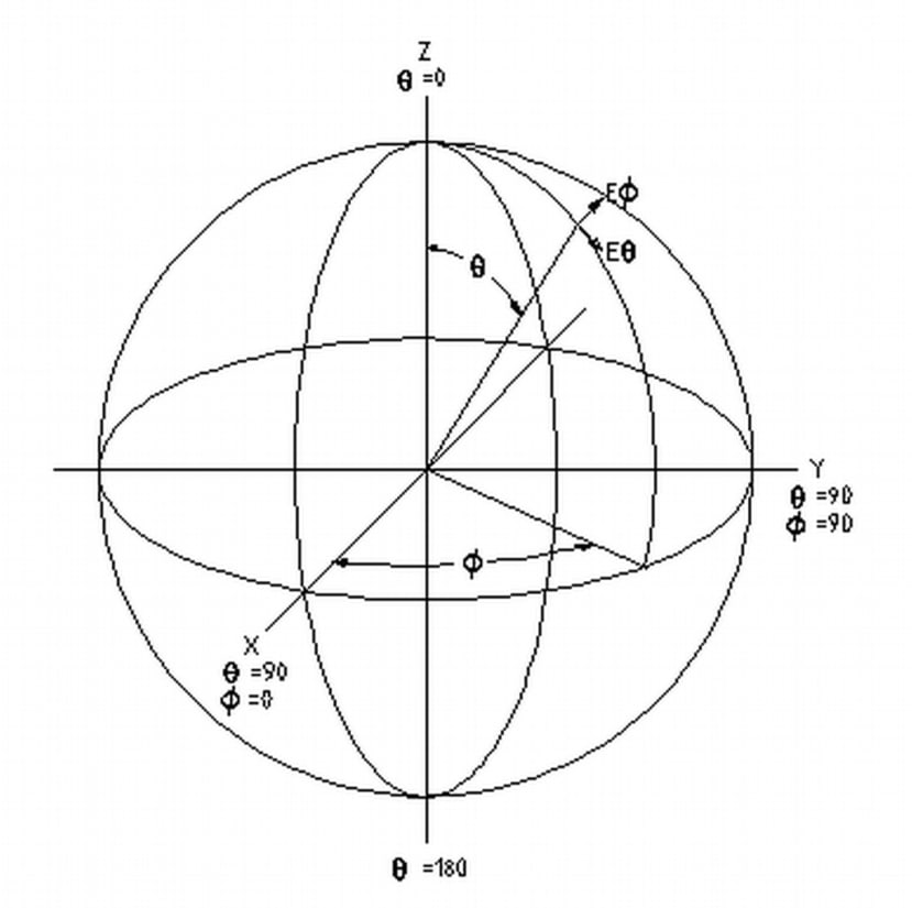
IEEE Std. 149-1979 Coordinate System for Antenna Measurements (source: EMCAR project)
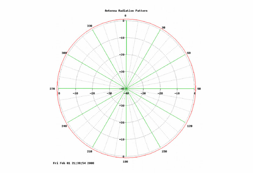
We are interested in measuring the antenna radiation pattern and in this case, the output will be a 2D polar plot. It’s possible that at some point in the future we may look to upgrade the design so that it can generate 3D plots, but 2D will be adequate for now and will show us the antenna gain in the forward/reverse direction and to the sides etc. The sort of information that is key when, for example, we need an omnidirectional antenna, one that is high gain and highly directional for a point-to-point link, or that has a narrow-angle and is suited to multi-antenna “sectored” use.
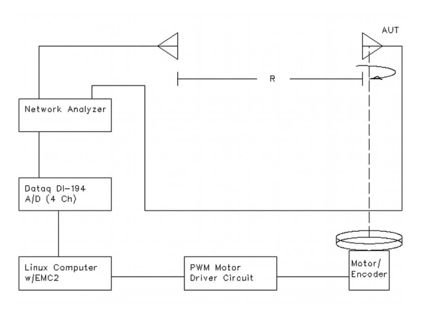
Antenna measurement system block diagram (source: EMCAR project)
The fundamental principle is actually quite simple and we have our antenna under test secured to a rotating platform, with a second, fixed antenna placed some distance away. Both are connected to an RF network analyser and as the first antenna is rotated, measurements are taken. Simple.
In our case we won’t be using a full-blown network analyser and rather instead a simpler, low-cost solution based upon the LimeSDR Mini software-defined radio (SDR).
Motor
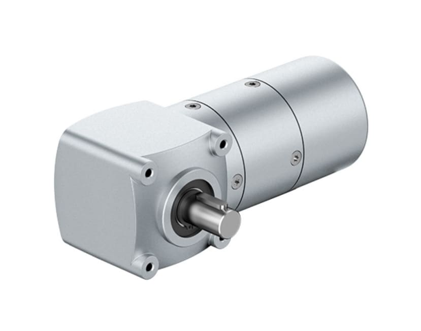
The motor is a key component and its performance will be linked to that of our measurement system. We need to be able to know precisely where the motor is and if we don’t want the process to take a long time, we need its movement to be very smooth (if it is not the antenna could be made to wobble and we might have to pause for a period between movement steps).
The motorised platform could be made as small or as large as you like. In our case we wanted to have something of a reasonable size and that, should the need arise, we could in future easily extend by securing a much larger platform to it. Such that we are then able to affix larger antenna structures to it directly, via a tripod or some other mounting. This means that we need a sturdy frame supporting the platform, a solid bearing underneath, and a suitably powerful motor driving it.
There are lots of options open to us and we could have gone with a stepper motor as used in the original EMCAR design. We could also use belts and pulleys to reduce the speed and in an attempt to create a smoother motion. However, we settled upon using an ebm-papst electronically commutated motor (187-2145) with integrated drive electronics and gearbox, which once programmed will provide an extremely simple interface for control and smooth movement.
Control
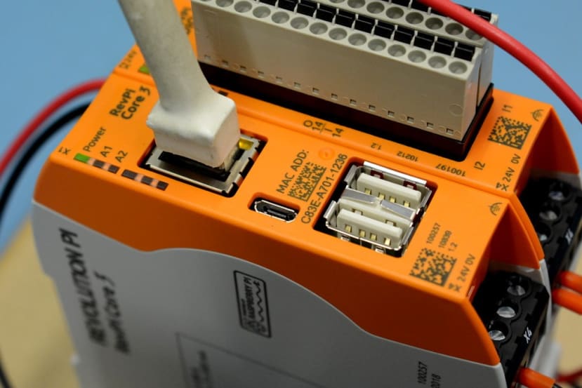
The control system will be based upon a Kunbus Revolution Pi Core (181-1141) , which can be extended with great ease to add plentiful industrial analogue and digital I/O. With this we have a variety of programming options available to us and we will most likely use a mixture of Python combined with existing C code from the EMCAR project.
RF measurement
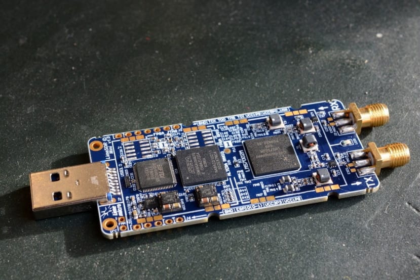
So now we have the means to rotate our antenna under test, and control its position and the measurement process, we need to actually carry out the RF link measurements. For this we will use the low-cost LimeSDR Mini SDR to generate signals on our frequencies of interest and to measure these signals at the receiving antenna.
Next steps
In the next post my colleague, Dave, will cover the design and prototyping of the combined enclosure for the electronics and mechanical support structure for the platform, together with the platform design, its bearing and motor coupling.