Testing Op-amp Circuits With The Analog Discovery 2
Follow article
 Dave from DesignSpark
How do you feel about this article? Help us to provide better content for you.
Dave from DesignSpark
Thank you! Your feedback has been received.
Dave from DesignSpark
There was a problem submitting your feedback, please try again later.
Dave from DesignSpark
What do you think of this article?
Using the Digilent Analog Parts Kit and Analog Discovery 2 to evaluate the performance of op-amps.
In the post, Discovering the Analog Discovery 2, I began sensing Déjà vu when I realised this seems quite similar to something I used a little while back, the Analog Devices Active Learning Module ADALM1000 (890-4004) . While both devices have measurement capabilities they seem to be aimed at different target audiences, but both have optional add on component kits which highlight their capabilities– the Digilent Analog Parts Kit and the ADALP2000 (890-4008) Analog parts Kit.
Component Kit Comparison
Both kits contain a range of ICs, sensors, resistors, potentiometers, capacitors, transistors, LEDs, diodes and inductors. The two kits are almost identical and after sifting through a list of the components and part numbers I realised there are only a small handful of minor differences. For example: the Digilent kit uses the CD4007 transistor instead of the HEF4007, and Digilent also uses a 10MOhm resistor instead of a 5MOhm resistor which the ADALM1000 uses.

I distinctly remember from working with the ADALP2000 Parts Kit previously that there are loads of great tutorials available on the Analog Devices website. What I loved about these is that they guide you through using the components in the kit with the ADALM1000 and allow you to begin as basic or advanced as you feel comfortable with.
When I looked through the Digilent website I found a really cool series of blogs called Getting the Most From The Analog Discovery 2: A Series, which entails a total of 7 labs covering a range of things from RC circuits to SPI communication. While these labs are great what I really wanted to do was crack on with the parts kit – I struggled to find any tutorials or projects using the ICs in the Analog Parts Kit for the Analog Discovery 2.
As the Digilent Analog Parts Kit and ADALP2000 Parts Kits are incredibly similar and use the majority of the same components, I decided I would repeat the amplifier projects which I completed previously using the ADALM1000. By doing this I could refer back to the Analog Devices Wiki page for their tutorials while being able to compare the ADALM1000 and Digilent Discovery 2 fairly.
Revisiting Op-amps
When it came to repeating the projects what I first noticed is that the op-amp used the first time round (OP97) isn’t included in the Digilent Analog Parts Kit. I did see however that the OP27 and OP37 op amps are included, so I began checking out their data sheets to see if one of these would be a suitable replacement.
From looking at the data sheets I saw that the OP97 is a low power alternative to the OP07 precision amplifier. The OP37 and OP27 seem very similar to one another at first glance and I soon noticed that the OP37 has the same high performance as the OP27, but the design is optimised for circuits with a gain greater than 5. The OP37 is also a replacement for the OP07 — as this is a replacement and the OP97 is an alternative, I thought that the OP37 would be a suitable alternative to the previously used OP97 to be used in the following projects.
Unity-Gain Amplifier
While the pinout of the OP97 and OP37 are very similar they are not exactly the same, so I had to double-check this before I could make any connections. The only pins required for this first step are pins 2,3,4,6,7 – of which both ICs have the same pinout for.
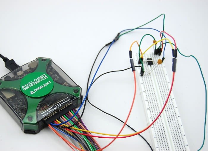
To begin with I connected up the example for the unity-gain amplifier and here I connected the Analog Discovery 2 to the circuit like so:
| AD2 | Circuit |
|---|---|
| V+ | V+ |
| V- | V- |
| GND | GND |
| Wave Gen 1 | Pin 3 |
| Scope 1+ | Pin 3 |
| Scope 1- | GND |
| Scope 2+ | Pin 6 |
| Scope 2- | GND |
The voltage supply pins V+ and V- were connected to +5V and -5V respectively.

The WaveForms software was then set to provide a 1V (2V P-P) 1KHz sine wave.

Here we can confirm that this is a unity-gain circuit as Vin = Vout. Below you can see the measurement at the input (Channel 1) and the measurement at the output (Channel 2) - The channels have been set on different voltages per division so we are able to see them both clearly.

Buffering amplifier
To begin with this type of circuit may seem completely useless as Vin = Vout like the previous circuit, so wouldn’t this just be the same as a unity-gain amplifier? The answer to this is no, a buffering amplifier is very useful as due to how the components and amplifier are arranged it means that we can avoid putting excessive load on a circuit.

This time we set a 1KHz sine wave at 2V (4V P-P) – In the oscilloscope we can see the input and output are exactly the same (unity gain). Initially I questioned why the input and output voltages in the scope only had an amplitude of 1V when I had set wavegen to produce a 2V (4V P-P)sine wave. I soon realised this was due to the two 4.7K Ohm resistors forming a voltage divider at the input, hence half the voltage.

Inverting amplifier
When I had wired up the inverting amplifier circuit and connected this to my PC I set the input signal to a 1KHz sine wave with an amplitude of 1V, however when I looked at the output of this I could see that this was clipping.

Knowing:
Vout= - (Rf/Rin) Vin
the gain of this circuit should be 4.7.
We can see from the oscilloscope above that the sine wave is clipping at approximately 4.3V. Initially I couldn’t understand why the wave was clipping; I had a suspicion that it may be to do with the op-amp used so I decided to double check the data sheet.
In the data sheet I saw that the OP37s design is optimized for circuits with gains greater than five, so I began to question if this could be the problem. Although 4.7 is very close to five it’s still
To try and overcome this I amended the Rf value and changed this from 4.7k to 10k to achieve a gain of 10. When I looked at the output of this the clipping appeared to be much worse than before.

After more reading I soon realised that the clipping was because the gain(amplified voltage) cannot exceed the supply voltage, as this configuration exceeded the supply voltage it began to clip at this point. To overcome this I changed the settings in the software to produce a 1KHz sine wave with an amplitude of 200mV instead of 1V.
Here I knew that with a calculated gain of 10 and a supply of 200mV I would expect to see an output somewhere around 2V. As 2V is still well below the maximum supply voltage I expected to see a clear sine wave with no clipping.
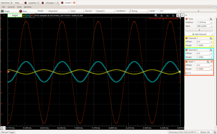
The new output signal was exactly what I expected to see! I decided to additionally include the math function in order to plot the gain alongside the input and output. To begin with I attempted to do this by dividing Channel 2(output) by Channel 1 (input) but the plot wasn’t what I anticipated. The result of doing this plotted a wave which appeared to be somewhere between a sine and tan wave…
To try and overcome this mistake I multiplied channel 2 by 5 as 1v/200mV = 5, doing this resulted in a plot of what I would have expected to see to begin with.

This was then repeated with the 4.7K Ohm resistor, this produced a clear sine wave without clipping. Once again I added the math function in order to see a plot of the gain along side the input and output voltages.
Looking at Amplifier Performance
I decided it would be quite nice to know the upper and lower frequency limits of the amplifier before this began effecting the gain. From the data sheet of the OP37 I could see that this particular device has a gain bandwidth of 63MHz. In order to determine the upper and lower frequency limits I began altering the frequency in the software and making a note of what effect this had on the gain and shape of the sine wave at each measurement.

From doing this I found that there is no effect on the gain of this amplifier between 10Hz and 200KHz. However, below 10Hz the gain began to drop and at 500mHz this dropped to 0.7. Above frequencies of 500KHz the sine wave began to look distorted and then the gain began to drop; between frequencies of 1MHz and 2MHz the wave looked very distorted and the gain dropped down to 3.

It may be that the wave produced between 1MHz and 2MHz would not have looked quite as distorted if I had used the BNC adapter board and the BNC oscilloscope probes, instead of using only jumper wires to carry out the measurements.
It would be interesting to see the effect that using the BNC adapter board and probes would have on the distortion of the wave at those higher frequencies to see if it distorts as much or even at all.
Overall I really like the Digilent Discovery 2! I think for its size its really powerful and the software is incredibly user friendly. In comparison to the ADALM1000 I can see that the Digilent Discovery 2 has capabilities to work with much more complex circuits, the oscilloscope readings are really clear and the WaveForms software is easy to navigate around and operate.