Robots: Avoiding Obstacles, Seeking Light
Follow article
 Dave from DesignSpark
How do you feel about this article? Help us to provide better content for you.
Dave from DesignSpark
Thank you! Your feedback has been received.
Dave from DesignSpark
There was a problem submitting your feedback, please try again later.
Dave from DesignSpark
What do you think of this article?

A number of my recent posts have covered aspects of robot sensor interfacing. Now I’ll look at a simple program that uses a sensor to help a robot move around without bumping into things, and another to steer it towards the light.
Avoiding obstacles
Once you’ve built your own mobile robot, programmed the Raspberry Pi or Arduino control board, let it loose and then watched as it crashed into the wall or fallen downstairs, you realise some sensor feedback would be useful. The simplest method, which doesn’t involve any digital electronics, uses simple ‘bump’ sensors made from lever-type microswitches (699-4746) . These can drive a change-over relay which reverses the power to the motors causing the robot to back off. This is not really obstacle avoidance, more touch and retreat. But it is simple and inexpensive.
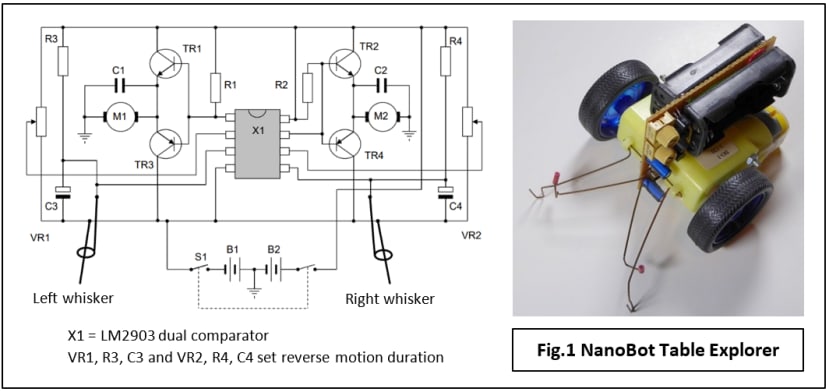
An even cheaper alternative is the wire ‘whisker’ which bends and closes a circuit when it hits an object. You can see how it works by looking at this picture of a minimalist robot I designed some years ago (Fig.1). Each whisker consists of a pair of springy wires and operates when the longer one is bent over and touches the fixed wire. The motor on that side is reversed while contact is maintained. However, if forward motion were resumed immediately when contact was broken, the robot would just keep head-butting the obstacle. An adjustable delay circuit is provided so the reverse motion continues for an interval after contact is lost.
Simple Single-Rangefinder Avoidance
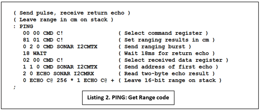
For non-contact detection of obstacles, the least expensive option is the ultrasonic rangefinder based on the sonar (sonic-radar) principle. As its name suggests, the device is designed to measure accurate distances up to a few metres, so it seems a bit extravagant to use it just to sense close proximity. It’s worth the investment if you intend to experiment with map creation and navigation later. Many hobby robots are supplied or can be fitted with a single fixed rangefinder on the front, facing forward. I fitted my trusty FORTHdsPIC robot with an SRF08 rangefinder module and programmed it for simple obstacle avoidance:
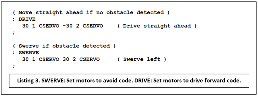
- If no object is detected or is more than 20cm ahead, then drive forward.
- If a detected object is less than 20cm away, swerve to the left.
Program listing for obstacle avoidance


Does it work?
Yes and no. An obstacle not much wider than the robot can be detected and successfully avoided both at long or short range. But if the object is a long, smooth wall across the path of the robot, the angle of approach has an important effect on its ‘detectability’ (Fig.2). If the angle is shallow – less than the ‘Critical Angle’ described in Robot Navigation with Sonar – then the reflected signal which should return to the rangefinder’s receiver, instead heads off in the wrong direction. The effect is to make the wall sonar-invisible to the robot.

The problem is easy to demonstrate with this robot: set it going on a perpendicular trajectory towards a wall. Painted skirting boards make excellent sonar reflectors. At the detection distance of 20cm, the robot veers to the left but stops turning when it reaches the critical angle. From now on it drives straight ahead until it crashes into the wall.
Soft furnishings can be invisible to sonar from any angle; in this case, it’s because they absorb all the ranging pulse energy and nothing is reflected. So, in response to the question ‘Does it work?’, the answer is: Yes, if you just want the robot to avoid running into relatively small, hard objects. No, if it encounters long ‘walls’ made of hard or very soft materials. More sensors are required to deal with walls, something I’ll be looking at in a later article.
Photovore
What’s a Photovore? In mobile robot terms, it’s a vehicle that heads towards a strong light source such as a torch. By itself it’s not a particularly interesting behaviour and is more usually combined with others, such as obstacle avoidance or wall-following, to emulate the response of a natural creature to its environment. Here though, I’ll just present some code that illustrates the need for more than one sensor when a robot has to move toward something rather than avoid it. The basic principle is shown in Fig.3 with a phototransistor-equipped mobile robot, one sensor on each side facing forward.

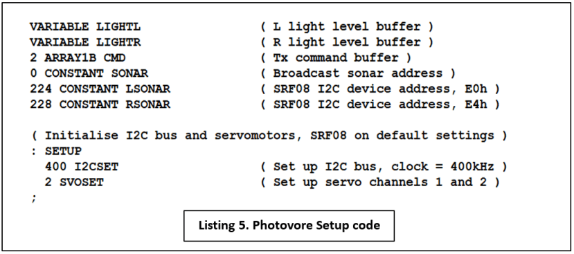
The SRF08 module includes a light sensor conveniently accessed via the I2C bus supplying an 8-bit light intensity value in the range 2 - 3 (Dark) up to 255 (Very Bright). An alternative is to use a Light-Dependent Resistor (LDR) such as the NORPS-12 (914-6714) with a pull-up resistor, connected to an analogue input on the microcontroller.
Program listing for light-following
Although no range readings are taken from the rangefinder modules, it is necessary to trigger a ranging pulse to sample the light sensor. As mentioned above, it’s rather an annoying feature of this device that it becomes unresponsive on the I2C bus until the pulse has returned or timed-out. Because the range-finding settings are left with their power-up values, this means a WAIT of at least 65ms is needed before the light value can be read. I decided to play safe with 100ms.

SENSE triggers the ranging pulse, waits for 100ms and then reads back the light values into variables LIGHTL and LIGHTR. Note the use of the I2C broadcast address (00h) to trip both SRF08s simultaneously. Obviously, the individual I2C addresses are necessary for reading the data.

DARKCHK checks to see if there is any light source to follow and if not, STOP will bring the robot to a halt. The threshold values can be found by experiment; ideally, they should be as low as possible without ambient light causing false movement. In practice, the robot will work in dim lighting conditions – total darkness is not required! STEER contains the code that uses the light values to calculate an appropriate speed for the right-hand motor. Slowing the motor causes a steer to the right, speeding it up veers the robot to the left. With no steering input, its speed setting is +40. The left-hand motor runs at a constant speed of -40.
- Subtract right sensor value from left.
- Limit the maximum values of the difference to ±30.
- Add the difference to nominal RH speed of +40. This yields a minimum speed of +10 and a hard right turn, to a maximum of +70 and a hard turn to the left.

As with the Avoidance code, MAIN is the top-level program loop which brings all the above definitions together and is pretty easy to understand.
Proportional control
What we have here is a PID controller with just the (P)roportional component implemented. It means that as the difference (or error) value falls, the steering input falls, making for less abrupt movements than those of the obstacle-avoidance robot. At least in theory. One drawback with using the wheel on one side only for steering is that the turning radius is not the same for both right and left turns. With full right ‘lock’ the inside wheel is barely rotating or may actually be stationary, hence a very tight turn. On full left lock, the inside wheel is still turning at its constant speed of 40, making the left turn a lot more leisurely when compared with the right. Things can be evened up by applying steering input to both wheels, but it may not be necessary: once the robot is ‘locked-on’ to a stationary light the steering corrections are going to be very small, so right-left variations are not going to matter much. On the other hand, a more consistent approach may be required if the light is moving randomly and the robot has to keep re-acquiring track.
The twin-sensor, difference-error technique for following a light can be adapted for use in two other, perhaps more practical situations with the addition of a light source (infrared LED) on the robot providing a simple version of Lidar. The range is very short, a few centimetres, so it’s not going to replace ultrasonics for long-range measurement applications. But how about:
- Floor-facing sensor unit for following a line drawn on the floor.
- Sideways-facing sensors (one on each side) for wall following, for example, in a Micromouse maze.
- Electronic replacement for mechanical ‘whisker’ proximity or bump sensors.
What’s next?
Clearly for robot sonar to be useful, the problem of invisible walls must be tackled. The simplest method is with the use of multiple rangefinders; the second is much more interesting – make a sonar-scanner by mounting the module on a conventional servomotor. The subject of a future post, I think! Full details of FORTHdsPIC for the Clicker 2 microcontroller board can be found on the project page.
If you're stuck for something to do, follow my posts on Twitter. I link to interesting articles on new electronics and related technologies, retweeting posts I spot about robots, space exploration and other issues.