Raspberry Pi Pico Piano – Part 3
Follow article Dave from DesignSpark
How do you feel about this article? Help us to provide better content for you.
Dave from DesignSpark
Thank you! Your feedback has been received.
Dave from DesignSpark
There was a problem submitting your feedback, please try again later.
Dave from DesignSpark
What do you think of this article?
In the previous chapter, we built a Raspberry Pi Pico Piano to play two notes simultaneously. If you haven't checked out that article, welcome to check it out (Raspberry Pi Pico Piano – Part 2). Then, in this chapter, we will move on to the hardware part.
We know that the output PWM signal of the Raspberry Pi Pico is a square wave. But in music, all notes are in Sine waves. To make it more likely a piano, in this chapter, I will share how I make a Square to Sine wave converter and an amplifier to amplify the output level.
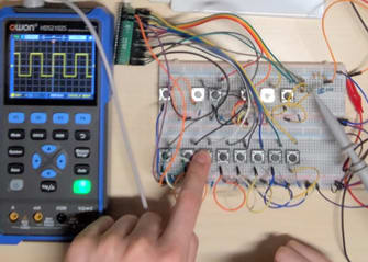
First, let’s see how the output PWM signal by the Raspberry Pi Pico is. Below, I used an oscilloscope to measure the PWM signal by the Raspberry Pi Pico. We can see that there is a Sine wave outputted.
Then, I tried to use an RC Low Pass Filter to reject the high frequency.
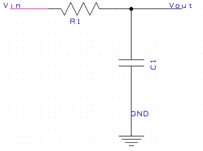

After I put the first RC stage, we can see that the output signal becomes more like a sine wave, which is an excellent start to making it a real piano.
Let’s try to implement the second RC stage to see whether the output signal can become more like a sine wave.
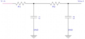
The output sine wave looks better. But having it as a sine wave still goes a long way. Let’s add one more RC stage.
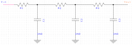
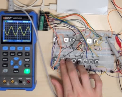
Now, we can observe a perfect sine wave. However, the trade-off is that we reduce the output signal level.
To calculate the output signal, the output signal will be reduced for each RC stage.
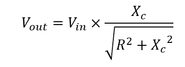
Hence, we need to think about how to amplify the output signal.
For the amplifier part, I chose the LM386 RS Stock No: (124-4528) . LM386 is a low voltage audio power amplifier. In this project, I directly used a USB for the power source for the amplifier, which means 5V input. For the circuit design, I followed the datasheet, which has a circuit diagram of LM386 with Gain = 50. The load impedance is 4 Ω to 32 Ω and the supply voltage is 5V to 12V.
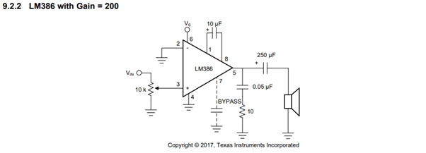
https://www.ti.com/lit/ds/symlink/lm386.pdf
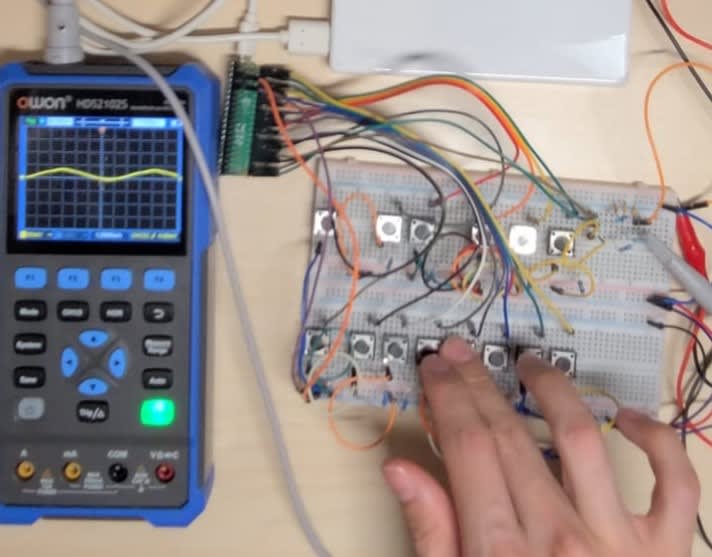
After I tried this schematic diagram, which had an excellent performance. But, because I implemented it on a breadboard, there are many noises. I wanted to implement it on a matrix board to perform better and reduce the noise to solve this problem. Also, in the matrix board, I added an on-off button and a LED light on the circuit to show whether the amplifier is powered on or off.
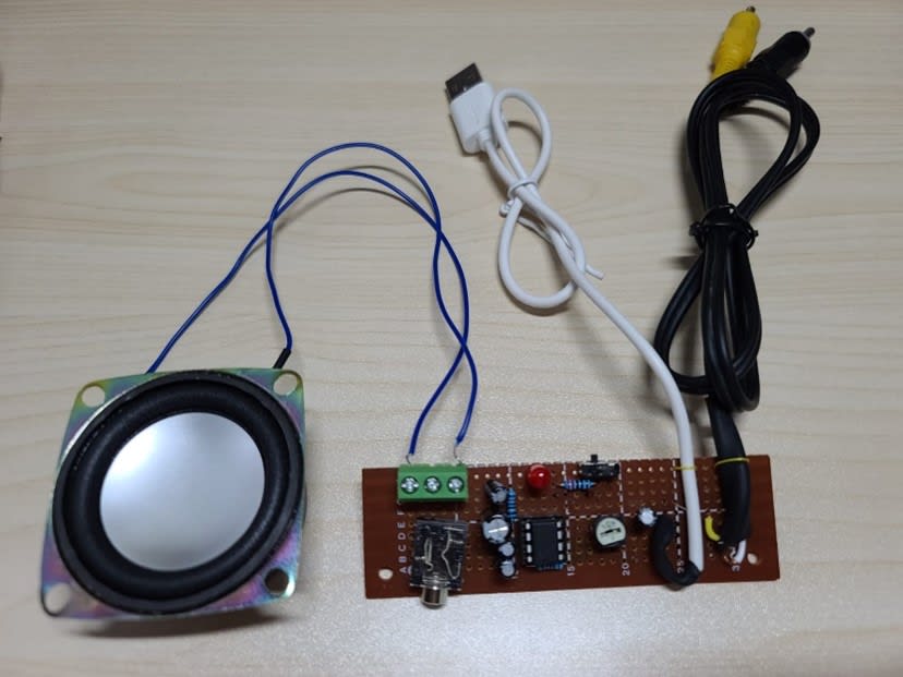
As you can see, I use an RCA cable for the signal source and a USB cable. I used a 3.5mm jack and 3 pin screw connector for the output. 2 pin screw connectors are enough, as they are mono outputs.
After I have the audio amplifier, I can combine all parts.
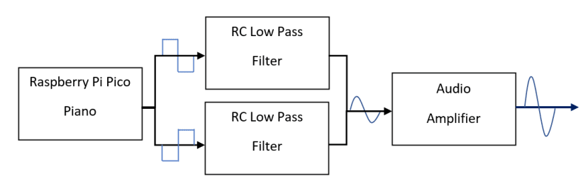
In the above flow chart, we can see two RC low pass filters as the piano can play two notes simultaneously. Hence, I put two RC filters in the circuit.
Finally, I made the final version of the Raspberry Pi Pico. This is an excellent experience for me to implement this project. I hope you can enjoy this series project.