Porting FORTHdsPIC to a MikroElektronika Clicker 2 Board
Follow article
 Dave from DesignSpark
How do you feel about this article? Help us to provide better content for you.
Dave from DesignSpark
Thank you! Your feedback has been received.
Dave from DesignSpark
There was a problem submitting your feedback, please try again later.
Dave from DesignSpark
What do you think of this article?
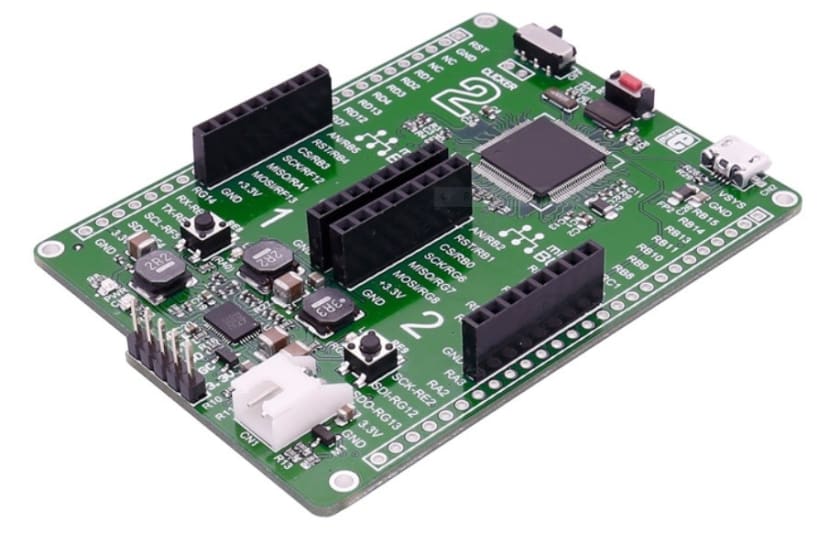
MikroElektronika Clicker 2 for the dsPIC33 Digital Signal Controller
Stalwarts of DesignSpark may remember my occasional posts on ‘Bare-metal coding’ based on my project to create an embedded version of the programming language Forth for the Microchip dsPIC33 Digital Signal Controller chip. Up to now, I’ve been using the 40MIPS FJ 28-pin DIP part on either a Microstick II or Arduino-format development board.
Clicker 2 for the dsPIC33: what does it offer?
Just a bit bigger than a standard Arduino, the Clicker 2 processor development boards contain few frills and could be built into a target application. The reason for my interest is twofold: a bigger, faster version of the dsPIC33 (Part number DSPIC33EP512MU810) and a neat board with a pair of Click expansion board sockets. The old 28-pin FJ chip I’d been using had enough memory, but too few timers and a very limited number of I/O pins. The newer EP device has more of everything plus some useful extras including a USB interface. The only other significant device on the board is a power management chip (PMIC) which provides the necessary supply voltage from a variety of sources including the USB socket, expansion sockets and even a Li-Polymer rechargeable battery pack.
Adding a Click expansion board
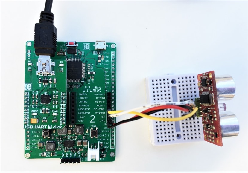
Actually, that internal USB interface was a bit of a problem: FORTHdsPIC’s terminal port is based on a serial UART protocol which gets converted to USB by an external ‘bridge’ chip. I didn’t fancy writing the necessary driver code to use the onboard USB connector so I located a suitable UART-USB Click board (Part number MIKROE-3063) to provide the terminal port.
Software changes
Just making the existing version of FORTHdsPIC work on the new board involved two main changes:
- Updating all constants that determine system and peripheral clocks.
- Reallocating I/O to different physical device pins.
Altering all the timing values was relatively straight forward. The first value to be changed was the PLL divider for the master oscillator, increasing the 40MHz clock to 70MHz. The clock frequencies for communication interfaces such as UART1 and I2C1 needed to remain the same of course, which means new values for their baud rate generator registers to reflect the increase in the system clock signal FCY. Similarly, Timer values for the Forth delay function WAIT, 50Hz PWM clock and rotation sensor (tachometer) clock were also recalculated. In most cases, the ‘recalculation’ merely involved multiplying the old value by 1.75 (7/4).
Moving the external connections to new pins is rather more complicated. A big feature of the dsPIC is the way that internal function inputs and outputs can be linked under program control to the physical pins on the chip. Not all permutations are possible and on a small device, like the 28-pin DIP version I used before, there is a limit to how many functions can actually be used at the same time. The Clicker 2 board has a 100-pin chip and many of its pins are accessible via the two MikroBUS Click sockets and two 26-way headers on each side. Writing the code to perform the pin allocation took a bit of time and much head-scratching. For example, a lot of the pins can be used for analogue inputs, and those pins default to that state on power-up or reset. If you want a particular pin to be a digital input, then the appropriate bit in that port’s ANSEL register must be cleared by your program. I wasted some time looking at a command prompt on the terminal screen while getting no response from the keyboard input until I realised what was going on!
Development software
The Clicker 2 is supplied in a piece of folded cardboard printed with ‘get you started’ instructions. These assume you have to hand the compiled program code in the form of a .HEX file on your PC which can be blown into the Flash memory via a USB link, using a free-to-download ‘Bootloader’. To create that .HEX file you appeared to need a suitable compiler available from MikroElektronika (not free) and for debugging, a MikroProg programmer/debug module. Hmm, annoying.
For the earlier versions of FORTHdsPIC the development tool I used was Microchip’s free-to-download MPLAB 8 IDE, which included a free version of a C compiler/assembler running on my PC while driving the target board via PICkit 3 or ICD 3 programmer/debug hardware. The question was: does MPLAB and its compiler create .HEX files and are they of the right format for the Clicker 2 bootloader? Fortunately, the answers are ‘Yes’ and ‘Yes’. The .HEX file format, also known as Intel Hex, was devised by the ‘inventors’ of the microprocessor many years ago for the very same purpose of downloading program code into processor chip memory. The format is very simple and consists of ASCII-coded hexadecimal numbers representing the executable code. Open a .HEX file with a text editor such as Notepad and take a look.
I also discovered (from the Clicker 2 user manual) that the board’s programming/debug 5-pin header normally used by a MikroProg module would work with my Microchip ICD 3, just by changing the cable’s pin assignments.
Now I had two ways of getting from the FORTHdsPIC source code in a .S text file to a fully programmed dsPIC33 on the Clicker board. Neither involved me spending any more money:
- Use MPLAB (upgraded to version X by this time) to create a .HEX file. Then use the free MikroBootloader program to Flash the code into the dsPIC memory.
- Use MPLAB as before to compile the source code, but now benefit from its own programming and debug features thanks to the ICD 3 and a modified cable.
What’s next
Now the original functionality has been restored, I want to investigate new EP features such as the ability to ‘nest’ the hardware DO…LOOP function up to four levels deep. With more timers available I should be able to improve the rotation sensor code (see this post). On the other hand, a development board for the new dsPIC33CH variant has just arrived. That’s a dual-processor chip as opposed to just dual-core, with yet more enhanced features. And they run a whole lot faster too. If I get around to producing a fully functional new version 0.8 of FORTHdsPIC, I’ll append the source and HEX files to this post.
If you're stuck for something to do, follow my posts on Twitter. I link to interesting articles on new electronics and related technologies, retweeting posts I spot about robots, space exploration and other issues.