Multiple Batteries A Balancing Act
Follow article
 Dave from DesignSpark
How do you feel about this article? Help us to provide better content for you.
Dave from DesignSpark
Thank you! Your feedback has been received.
Dave from DesignSpark
There was a problem submitting your feedback, please try again later.
Dave from DesignSpark
What do you think of this article?
Without battery balancing, the weakest cell in a multicell battery always determines the capacity of the entire system. However, since individual cells age differently, it is not possible to ensure that all cells have the same capacity, even with a conscientious selection. It needs different approaches.

Lithium-ion batteries, like other battery types, are subject to a process of wear and tear during charging and discharging due to chemical changes. In the lithium-ion battery, the anode consists of a copper foil coated with carbon or a graphite compound. The cathode consists of a lithium compound. The electrolyte between the electrodes is a dissolved lithium salt. Depending on whether the electrolyte is liquid or solid, one speaks of lithium-ion or lithium-polymer batteries.
The cells differ mainly in the cathode material, which can consist of cobalt, manganese, nickel-cobalt, nickel-cobalt- manganese (NKM), iron phosphate or titaniumate. The various cathode materials cause different energy densities, power densities, nominal voltages and possible charging cycles.
Smooth charging
The so-called IU charging method, which is used for such cells, works with constant current and constant voltage (Constant Current = CC, Constant Voltage = CV). In this procedure, the batteries are first charged with a constant current. This limits the charging current, which prevents this to be too high. Constant current charging continues until the final charge voltage is reached. Afterwards, charging is continued with constant voltage, so that the final charge voltage cannot be exceeded. The charging current decreases with increasing charge.
Like the lifespan, the charging time also depends on a number of factors, with higher charging capacities, above all on the temperature. Short charging and discharging times have a negative effect on the electrode material, so that the lifespan and number of cycles are shortened. Smooth charging and discharging increases the lifetime of a lithium-ion cell massively!
Lithium plating
Charging lithium-ion cells at high charging currents or low temperatures can lead to the damaging effect of lithium plating. Lithium ions preferably deposit on the anode surface instead of intercalating between the layers of graphite. This effect results in significant losses of performance, durability and safety. In extreme cases, lithium plating can even lead to a short circuit or, as metallic lithium is quickly flammable, to a fire.
Depending on the quality and design of the battery, 500 to more than 1000 charging cycles are common. A battery is considered worn when less than 80% of its original capacity is left.
The Problem
So-called clusters or battery packs generally consist of several single cells or cell blocks connected in series to increase the nominal voltage. Due to and ageing there are fluctuations in the capacity, internal resistance and other parameters of these cells. The weakest cell determines how much is loaded and how much may be unloaded.
In the practical use of multicellular batteries connected in series, this leads to the fact that the cells are charged and discharged differently in series. Critical deep discharge or overcharge occurs in the network or when individual cells overcharge and exceed the final charge voltage. Depending on the type of battery, irreversible damage to individual cells may occur. The result: the entire battery pack loses capacity.
Battery management systems (BMS)
BMS are responsible for controlling and monitoring the charging and discharging process of high-performance battery packs in autonomous power electronics applications (E-Power) such as electric and hybrid vehicles, robotics or similar. Its main task is to ensure that each individual cell does not exceed or fall short of a defined state of charge (SoC) limit for the application, both during loading and unloading. The SoC value is the remaining available capacity of a battery in relation to its nominal value. The value is given as a percentage of the fully charged state. Example: 30 % means that the battery still has a residual charge of 30 % relative to the full charge. Depending on the application, the upper and lower limit values for the SoC are 20% - 100% (max. power) or 100% (max. power). 30% - 70% (max. service life).
A BMS monitors characteristics such as battery voltage, cell temperature, cell capacity, charge state, current draw-off, remaining operating time, charge cycle and much more. These control units are essential as several battery cells have to be clustered to achieve a high total battery capacity. Balancers play an increasingly important role in such battery management systems.

[1] High discharging stress leads to reduced lifetime
[2] High charging stress leads to reduced
Battery Balancing: passive
A technically relatively simple and widely used method is passive balancing. This works practically only at the end of charging when the cells of a battery pack are almost completely charged. For those cells that have already reached the final charge voltage, a resistor is connected in parallel by the balancer, thus limiting the voltage to the final charge voltage. This cell is then only slightly charged or even discharged, while the cells in the series connection, which have not yet reached the final charge voltage, continue to be supplied with the full charge current. The power of the parallel resistor must be adapted to the charging current, since the excess energy occurs in the form of heat at the resistor. The advantage of this method is that it is inexpensive and technically easy to implement. The other side of the coin: the charging process takes so long until the weakest cell has reached the required SOC value. In addition, a lot of energy is wasted in unwanted heat. This heat loss also has a negative effect on the service life of the battery cells and represents a considerable fire hazard.
Battery Balancing: active
Active balancers are much more complex but more efficient. They are used to transfer charge between cells: the energy of cells with a higher charge is transferred to cells with a lower charge. In principle, the charge control consists of several switching regulators which are specially optimized for the application and which operate per cell and actively transfer energy. This process can already take place during the loading process. However, as with passive balancing, it usually only starts in the area of the charge end. In bi-directional balancer systems, this charge exchange takes place during both the loading and unloading process. Bidirectional balancers are therefore even more efficient.
A major advantage of active balancing is the significantly higher efficiency, since surplus energy is only converted to heat to a small degree. Active balancing is currently being used for larger outputs (e-power) in areas such as electric mobility (EV = Electric Vehicle, BEV = Battery Electric Vehicle, HEV = Hybrid Electric Vehicle and PHEV = Plug-in Hybrid Electric Vehicle).
The higher switching effort for the control system naturally results in higher initial costs. In return, however, this control system for battery management offers tangible advantages. By means of a superordinate charge control with intelligent and adaptive software, this charge redistribution of strong to weak cells - even across different series circuits - can significantly extend the service life of a high-performance battery pack.
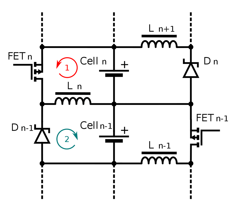
Principle circuit of an active balancer with coils, two steps. Source: wikipedia
Protection
In E-Power applications such as electric vehicles, battery packs are usually the biggest cost factor at all. The customer demands maximum performance capacity, the fastest possible charging process, long service life and absolute reliability. Requirements that are not simply compatible.
Lithium-base batteries have a significantly higher power density than robust lead- acid batteries. However, they are very sensitive to overvoltage and undervoltage. This requires monitoring and protection to reliably prevent premature failure, overheating or even short-circuiting of individual cells. Such backups must work faultlessly for many years. They have to withstand the winter cold and summer heat, as well as shocks and vibrations.
They must allow maximum charge and discharge currents to pass with minimal losses. Switching on and off, accelerating - cyclic resistance is also indispensable.

IU charging method with constant current (CC) and constant voltage (CV)
Customized fuses
However, the biggest enemies of battery packs are overtemperature, short-circuits and pulsed overcurrents. Depending on the design and purpose of the high-performance battery pack, the focus must be placed on protection against overcurrent and/or more on temperature. In most cases, however, several potential problems come together at the same time. In practice, this means that customized solutions are required for protection. Possible - and already implemented - are pulse-proof combination fuses for protection against overcurrent and overtemperature. This is done using chip technology to ensure the necessary mechanical resistance.
Maximum power density with maximum safety and longevity: this approach applies not only to the individual cells, but to the entire energy unit.
Economy
Of course, it is always possible to use the latest battery technology and always provide the highest possible performance capacity. However, this is always associated with high costs and long-term experience is completely lacking. For this reason, the industry tends to build on established technologies that have proven themselves millions of times in standard applications (e. g. notebooks). In a next step, manufacturing processes are optimized, the limits of the input and output flow are determined, and mechanisms for scaling as much as possible are developed. The intelligent charging and discharging process will be of enormous importance in the future. Optimized balancing combines maximum performance with maximum life expectancy.
Experienced partner
SCHURTER now offers a wide range of fuses according to AEC-Q200 for various applications (battery management, climate control, engine-related electronics for diesel/petrol engines and many more). Millions of fuses to protect against overcurrent and overtemperature as well as their combination are in use worldwide. The close networking with international automotive organizations and the industry itself make SCHURTER a competent partner for all questions concerning the protection of electronics in automotive engineering.