Intelligent RGBW lighting with MQTT and I2C
Follow article
 Dave from DesignSpark
How do you feel about this article? Help us to provide better content for you.
Dave from DesignSpark
Thank you! Your feedback has been received.
Dave from DesignSpark
There was a problem submitting your feedback, please try again later.
Dave from DesignSpark
What do you think of this article?

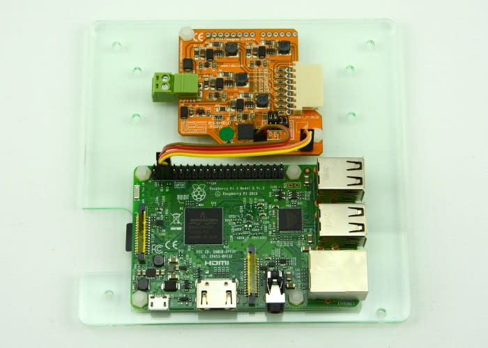
Using a Raspberry Pi and the RGBW LED board from IES
High powered LEDs are ubiquitous these days, to the point where traditional filament bulbs are being replaced in homes, professional venues, cars and even horticulture. It is possible to use a combination of red, green and blue LEDs to mix many different colours, whilst white LEDs come in a range of different colour 'temperatures' or hues.
The 4-channel RGBW LED module, or 'shield' from IES allows for colour mixing of up to 12 LEDs per channel, controlled via a standard I2C bus. This means that it is compatible with both the Arduino and Raspberry Pi platforms, amongst others. Further reading on I2C can be found here.
In this post we will take a quick look at the board, build it into an enclosure and control it with a Raspberry Pi via MQTT, a Machine-to-Machine (M2M) or Internet of Things (IoT) connectivity protocol that was designed to be extremely lightweight.
It will be assumed that you have root access to a Raspberry Pi on a local network, with an MQTT broker, for example Mosquitto, running.
In the box

The board comes bundled with a compact RGBW LED module strapped to a heatsink, to allow you to get started quickly without having to specify and source additional LEDs. Referring to the quick start guide, I began by soldering two pairs of header pins to the board, for connection of system power and SDA/SCL, required for control over I2C. Since we plan on using the board with a Raspberry Pi, two jumpers must be removed, disconnecting on-board pull-up resistors on the SDA and SCL lines that are required for use with higher I2C voltages used by the Arduino.

I then made up a simple mounting plate to hold the board in place alongside a Raspberry Pi, to avoid any disconnected wires or unwanted short circuits.
Though the main board takes power from the host controller, in this case an Arduino or Pi, a second power supply is required for the high power LEDs, of between 12 and 48 VDC. This varies according to the amount of LEDs connected, more detailed information on which can be found in the datasheet.
Getting it working

With the board wired up to a Raspberry Pi along with a 12VDC power supply, the system was booted and I2C enabled. This can be done using the raspi-config tool on more recent Pi models. To give Python access to the I2C bus, I then installed the Python module smbus:
$ sudo apt-get install python-smbus

Following a system reboot, it was then possible to see the board connected to the Pi's I2C bus, at the default address of 0x70, using the following command:
$ i2cdetect -y 1
Next, the demo 'RGBW.py' was extracted from the examples provided and copied onto the Pi. It was then executed as follows:
$ python RGBW.py
This first resulted in a permission error, since use of the I2C bus on the Pi requires root access. One workaround is to run the Python script as root:
$ sudo python RGBW.py
However, this is not best practice. Instead, adding the user 'pi' (the default user on the Pi) to the group 'i2c' is more suitable:
$ sudo adduser pi i2c
Following a reboot, the script can now be run as we first tried:
$ python RGBW.py
This time, a different error, requiring some investigation. Using Nano – a convenient and relatively user-friendly text editor – it was quick and easy to see the one line that needed changing, due to clear and useful commenting within the code.
With our edit made and the file saved, the demo script ran and the LED module cycled through a number of different colours.
With the LED module working, controlled by the Python script running on a Pi, we could start to build something a little more interesting.
Building a thing

Happy to stick with the supplied LED and heatsink for now, a simple enclosure for the board was laser cut, using some frosted acrylic sheet to act as a diffuser for the light. Holes were added to allow for some airflow for passive cooling, though the heatsink does not get particularly warm.

The board and module were removed from the first mounting plate and transferred to the new enclosure. This was then hung on the wall and connected to a Raspberry Pi in our workshop, that is already running different automation tasks via MQTT and Node-RED.
With the hardware in place and tested, we can now look to improving functionality and software control.
Software

Aims of the software:
- Control of RGBW LED via MQTT
- Ability to change colour and brightness
Referring to the example code, and the datasheet, I began to put together a Python script to control the RGBW LED, using the Paho MQTT Python client that can be installed by executing:
$ sudo pip install paho-mqtt

Referring to the datasheet of the LED board, it is possible to determine which registers out of the 20 in total we want to write to, depending on what we want to control. By cross-referencing the registers in the datasheet (shown above) and the numbers used in the demo code (shown below), it was possible to double check exactly which ones were required.

For example, it is possible to see that the datasheet shows the RGB red, RGB green and RGB blue registers numbered 3, 4 and 5 respectively, reflected in the code.
MQTT allows for messages, assigned to particular topics, to be sent and received. The payload, or content of messages is text. I decided to format my messages as a JSON object, making it easy to include multiple variables in one message.
Since mixing colours can be done in two different ways, either using RGB values or HSB (hue, saturation and brightness), I decided it would be useful to include a way to determine which method would be used, before writing values to each register.

The resulting Python code can be found in the repo. Executing the file from the shell with:
$ python RGBW-LED-Control.py
We get confirmation of the connection to MQTT broker, IP address and topic. A second shell session can now be started in a different tab or window.
The Python script connects to a local instance of Mosquitto, an MQTT broker – see a previous post for how we set one up – and is subscribed to the topic 'RGBW-LED'. We can now control it by publishing a message to this topic, either from a local machine, or another connected to the network.
An example publish command is:
$ mosquitto_pub -h 127.0.0.1 -t RGBW-LED -m '{"command": "RGB", "r": 80, "g": 60, "b":100, "w": 0, "hue": 0, "sat": 0, "bri": 0}'
This is run from the shell and does the following:
- connects to the local IP of 127.0.0.1
- publishes to the topic RGBW-LED
- sends the payload {"command": "RGB", "r": 80, "g": 60, "b": 100, "w": 0, "hue": 0, "sat": 0, "bri": 0}
- RGB defines that the colour control is using RGB values
- r, g and b sets values for RGB LED brightness
- w sets value for white LED brightness
- hue, sat and bri set values for hue, saturation and brightness
Note that the above command sends values for w, hue, sat and bri that are in fact not used for RGB control. In fact, the payload could be shortened to: {"command": "RGB", "r": 80, "g": 60, "b": 100} and still function correctly.
Further example payloads are:
- For control of the white LED brightness:
- {"command": "WHI", "w": 75}
- For HSB colour control:
- {"command": "HSB", "hue": 255, "sat": 50, "bri": 80}
Going forward

We now have a great working demo, with a Python script that can be run from the shell, or configured to start when the Pi boots. This example code provides a quick and easy way of controlling the RGBW LED board via MQTT, using a simple JSON message payload format.
We could now change the colour of the light according to readings of other sensors connected to our Pi, or network, for example a local temperature sensor. Additional LEDs and boards could be connected and controlled with some modifications to the code. With MQTT, the potential for IoT applications and automated control is vast and exciting!