Increase the safety of your commuter trips with this device
Follow article Dave from DesignSpark
How do you feel about this article? Help us to provide better content for you.
Dave from DesignSpark
Thank you! Your feedback has been received.
Dave from DesignSpark
There was a problem submitting your feedback, please try again later.
Dave from DesignSpark
What do you think of this article?

By Alberto Madurga and Manuel Lorrio
The objective of this device is to increase the visibility of a cyclist, while also allowing for basic vehicle-to-vehicle communication. A 16x16 LED panel located in the backpack is used as the billboard where the different screens (position light, emergency blinker, left and right blinkers, rear fog lights, and brake lights) can be selected. Meanwhile, a small remote control is placed on the handlebar of the bicycle to control all the different screens.
This project was part of the “Electronical Equipment Design” course in the last year of Master in Industrial Engineering at the Public University of Navarra, Spain (UPNA). The objective of this course was to design, produce, debug, and troubleshoot an electronics device of our own creation.
Hardware
This device is based on the Espressif ESP8266-ESP12F platform (see Figure 1) microcontrollers (a 3.3V system). The reason for that is their low power consumption, small form factor and built-in antenna. Furthermore, the ESP platform is able to use its own low-power communication protocol called EspNOW, which can only interact with other ESP devices (making it more reliable), and its own layer of encryption.

Figure 1: Detail of the ESP8255-ESP12F platform used for the project
The energy source for the LED panel was decided to be a 5V 4A 20000mAh external power bank, so that all users were already familiar with how to switch it on and off. For the remote, however, a simple 2 button battery CR2032 system was necessary. This would allow for a long battery life, and a simple process to change them when depleted.
Remote Controller
A 5-button switch membrane button from the Arduino components selection, and 2 digital hall effect sensors were chosen as inputs for the remote controller that selects the different screens in the LED panel. Whenever the user pushes any of the 5 buttons of the membrane, the corresponding screen is displayed on the LED panel. Regarding the hall effect sensors, they were connected to the bicycle’s brake levers, so that whenever the user needs to brake, the LED screen changes automatically showing the STOP signal. Both brake inputs were routed through an OR logic gate to reduce the number of ESP8266 GPIOs needed for the project.
Lastly, a small 128*36-pixel OLED was used as a user interface. This allows the microcontroller to communicate to the user which LED screen is currently being displayed on the LED panel, plus additional information, such as the battery status of the controller (measured by an x1/2 voltage divider) and whether both devices are properly connected or not.
A schematic representation of the connections between the modules involved in the remote controller is shown in Figure 2.

Figure 2: Schematic representation of the connections between the modules involved in the remote controller.
As part of the course project, an interconnection PCB was required to provide proper connections between the modules (see Figure 3). The PCB was designed and manufactured in-house. It was decided that the DesignSpark PCB framework would be the best platform to create the prototypes for this project. The design was made with a “1-layer” concept, meaning that all the tracks should be routed using only one of the 2 sides of the PCB. This approach reduces the costs as well as increases the manufacturing speed.


Figure 3: Electronic circuit (top) used for the design of the module interconnection PCB (bottom).
LED panel
Another ESP8266-12F microcontroller was used. In the electronic circuit governing the LED panel, this time, only the power pins and 1 digital GPIO were required. Since the LED panel was expected to draw a high amount of current, it was decided that a high-capacity capacitor would be placed in between the LED panel power supply and the microcontroller. This would prevent a voltage drop and a reset of the ESP8266 whenever there was a large current demand. The electronic circuit of connections of the ESP8266-12F with the LED panel and the final assembly are represented in Figures 4 and 5 respectively.

Figure 4: Electronic circuit connections of the LED panel with the ESP8266-12F

Figure 5: Assembly of the ESP8266-12F with the capacitor and connections with the LED panel.
Design
Since the first design t produced was a prototype, special care was taken in reducing the footprint of the PCB to its maximum expression. The use of through-hole components and a one-layer PCB design did not allow for a miniaturized version to be produced while meeting the project deadlines. Nevertheless, a case was designed as a tentative prototype to house the remote control (see Figure 6):
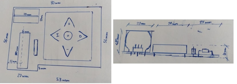
Figure 6: Case designed to house the remote-control prototype (Top view Left, Front view Right).
The 3D models of the controller case were done using the OnShape and AutoCAD-3D design software (see Figure 7).

Figure 7: 3D design of the case that houses the remote control prototype
Working Prototype
After all of the time and effort, the prototype was finally functional and the results show the different indications of the LED panel and OLED screen can be observed in the next images and the final video.

Figure 8: Image of the selection pad and the respective actions

Figure 9: Left blinker lights

Figure 10: Right blinker lights

Figure 11: Emergency lights


Figure 12: Alternating position lights

Figure 13: Rear fog lights

Figure 14: Brake lights

Figure 15: Remote controller screen (from left to right): Left Blinker, Emergency lights, Right blinker, Position lights, Rear fog lights, Braking light.
References
Link to the 3D models, PCB design, datasheets and code of the prototypes can be found in the download attachment below..