Incorporating a PanelPilotACE into the Red Tin Part Two: Stereo VU Meter, Fan Control and Monitoring
Follow article
 Dave from DesignSpark
How do you feel about this article? Help us to provide better content for you.
Dave from DesignSpark
Thank you! Your feedback has been received.
Dave from DesignSpark
There was a problem submitting your feedback, please try again later.
Dave from DesignSpark
What do you think of this article?
Stereo VU metering, fan control, and monitoring temperature and voltage in the Red Tin.

In the first part in this series, I outlined the first steps I took having decided the PanelPilotACE would make a good addition to the Red Tin for system monitoring, starting with a single channel VU meter that used an envelope follower circuit. In this post, I show how I expanded this into a two-channel stereo VU meter, added a temperature sensor that controlled a fan, plus a voltmeter.
Designing the PanelPilotACE Interface
I had decided I would have a “home” screen that displayed the essentials and also allowed me to click through to pages with more detailed monitoring information. I first made a simple 480 x 272-pixel grid with 6 sections using Inkscape and then exported it as a transparent .PNG file. This could easily be dragged into the PanelPilot Design Studio and would act as a guide for the elements of my home screen. The extra control over automatically arranging and aligning shapes in Inkscape made doing it this way easier than working directly in Design Studio.

I ended up with a home screen that features 2 versions of the VU meter – a bar graph and a needle, as well as temperature and voltage readings.

Each section is covered with a transparent rectangle that acts as a button that loads a screen with more detailed information when pressed. The VU Meter takes you to the two-channel version, for example. I intend to develop these screens further in the future to add fan speed and more detailed power monitoring, each of these screens has a home button to take me back to the main screen
I also added an analogue clock using one of the ready-made meters that come with Design Studio. It is always useful to know what time it is when you are DJ’ing.
Stereo VU Meter and Fan Control Circuit

In my previous post, I detailed how I made an envelope follower to connect to the audio out of the Red Tin and control a VU meter on the PanelPilotACE. This used a double Op Amp and so I could use the other half to power a second channel and give myself stereo monitoring. I put the circuit together on a breadboard, tested it and it worked the first time.
I now added the circuit to my breadboard for controlling the speed of a fan, that I had previously used in my first encounter with the PanelPilotACE. The difference this time was that I wanted the speed to be controlled by the temperature in the tin, rather than manually by varying the voltage of a bench power supply, as I had done previously.
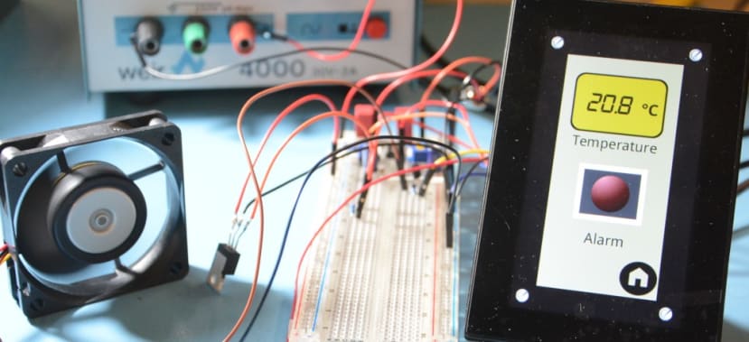
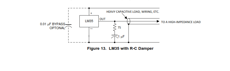
I used a Texas Instruments LM35DT Temperature Sensor (535-9458) and, referring to the comprehensive datasheet, put together the circuit with R-C damper and connected the output of the sensor to one of the analogue inputs of the PanelPilotACE. I adjusted the voltage settings for the input in Design Studio and after some trial and error, settled on a range of -1 to 5V. I also set the Temperature Display to map -1V to 0 and 5V to 100. This gave an ambient temperature reading of around 18C which, according to the thermometer in the workshop was about right. I could do with doing some more serious calibration to get more accurate readings, although, for the purposes of monitoring the temperature in the Red Tin and controlling a fan accordingly, I reckoned the settings I had arrived at should be fine.
I attached my fan (781-5058) and could hear it increasing speed as I increased the temperature using the workshop heat gun.
The voltmeter was simply a matter of connecting the remaining analogue input on the Panel Pilot to the input socket on my 12V Distribution box.
Fitting it in the Tin
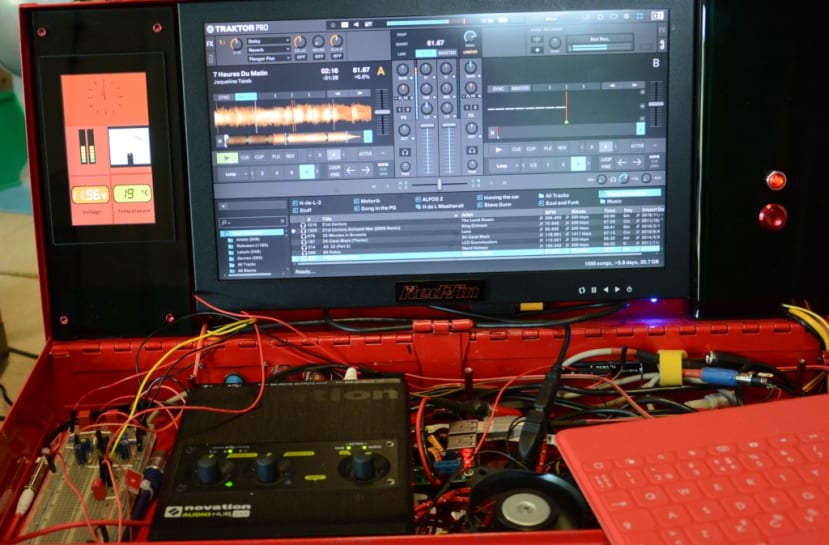
Space is getting a bit tight in the Red Tin, but with the PanelPilot in portrait orientation, it fits by the side of the main screen. This means I can read the vital signs at a glance as well as providing some additional visual interest.
At this prototype stage, the wiring is obviously untidy, but I can soon fix that. I also need to make the circuits I was using into something more permanent and compact using perf-board — then it could tuck away in the top section of the tin, next to the Udoo x86.
To-do List
It now remains to tidy up the circuitry and wiring, cut a new cover for the top section of the Red Tin to accommodate my new fan and work on the PanelPilotACE screens with the more detailed monitoring information, all of which I will cover in the next post.
I can also foresee that I will want to tweak the graphics and maybe add some warning lights to the home page, or maybe even set the PanelPilotACE to switch to the relevant screen automatically when critical levels are reached. That is the joy of the PanelPilotACE – I can keep adding to it and trying new things!