IMPlicit IoT Security
Follow article
 Dave from DesignSpark
How do you feel about this article? Help us to provide better content for you.
Dave from DesignSpark
Thank you! Your feedback has been received.
Dave from DesignSpark
There was a problem submitting your feedback, please try again later.
Dave from DesignSpark
What do you think of this article?
Electric Imp is out to tackle a growing Internet of things (IoT) problem with their Imp 005 Module. When was the last time you heard of some major hack or substantial data breach? If you read any tech media at all, it was probably this morning. The fallout from a breach is costly, not only in immediate fiscal terms - where a company will have to pour resources into rapidly mitigating the problem and can then find themselves subject to hefty fines by the authorities – there is also the (hard to measure) long-term damage to the company’s brand name.
The spill-over of all these bleak news stories to IoT projects is that many potential customers now see IoT devices simply as security breaches-in-waiting. They have a point: why would anyone want to install a device that is, at best going to be hijacked into being part of a botnet or, more seriously, offer a soft access point to their network?
Electric Imp
This is where Electric Imp reckon they can make a difference. The company is headed up by Hugo Fiennes, who led Apple’s hardware team for the first four generations of the iPhone before going on to design the Nest thermostat. Electric Imp already has some impressive design-ins for their kit, including the likes of Eaton, GE and Pitney Bowes.
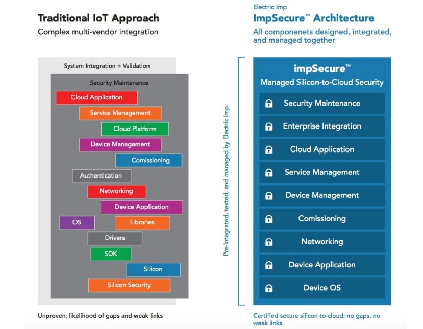
The difference Electric Imp feel they can make is in network security. They have obviously thought long and hard about all the possible attack vectors to which IoT applications might be vulnerable. From there, they have developed a ground-up approach to negating each attack vector that even sees external hardware interfaces disabled after the cryptographic keys and code have been safely loaded onto the silicon in the factory. Their hope is that developers will adopt Electric Imp’s fully integrated and tested edge-to-cloud architecture rather than spending months developing their own or integrating multi-vendor solutions to connectivity.
Imp005 Module
The imp005-EZ module itself comes with:
- Murata Type 1GC (based on Cypress Semiconductor's CYW43907) SoC Cortex-R4, 320 MHz CPU with up to 1 MB RAM for application code, which equates to around 15k lines of user code.
- 8MB on-board boot SPI with 4.5 MB free for applications
I/O mechanisms:
- Dual-band Wi-Fi with onboard antenna (FCC/IC approved, CE tested)
- 3x UART, 1x SPI, 1x I2C, USB host
- 19x GPIO (muxed I2C, SPI)
- RMII Ethernet
And a Blinkup circuit & RTC crystal for commissioning.
Evaluation Board
The imp005-EZ can be bought already mounted onto the Eval board, which provides physical connectors for all that I/O:
- Dual-band (2.4GHz + 5GHz) 802.11abgn Wi-Fi, integrated antenna
- WAN Ethernet via RJ45 connector
- USB 2.0/1.1 Low-Speed/Full-Speed host
- Arduino Shield-compatible headers (3.3V)
Plus access to some sensors:
- HTS221 Temperature and humidity (136-0755)
- LIS2DH12 Motion in three axis (Rev 2) (878-7465)
- MCP3208 ADC connected via SPI (379-2516)
….and, of course, the trusty application-controlled LED:
- APA102 RGB LED
Workshop
To give you a flavour of developing with an imp005 module and whether it might be something that would fit an application of your own, I will take you through a workshop I did a few weeks back with the folks from Electric Imp.
There are a few things you need before you get going.
Equipment List
- Laptop with Wi-Fi connectivity – This is where you will control the project
- iPhone or Android phone – To provision the module with local Wi-Fi login information
- Arrow imp005-EZ-Eval kit + mini-USB cable for powering the module
- Wi-Fi Access Point to provide Internet connectivity – note that you will not be able to use an open network with login page setup for connecting the imp module.
You will also need to:
- Install the BlinkUp app on your iPhone or Android phone – You can find it by searching iTunes or Google Play for “Electric Imp”
- Create an Electric Imp developer account at https://electricimp.com/docs/gettingstarted/developer/account/
- Create an IBM Bluemix account – I will show you how to do this later in the article.
What we are trying to do is represented by the following diagram:

As you can see, we are simulating a ‘smart’ refrigeration system. The imp005 module is set up to monitor the temperature, humidity and light conditions of our fridge and generate alerts should these values stray outside set parameters. To save power, the device batches data readings to send in one go and disconnects from the server and runs wi-fi in power save when not transmitting.
The endpoint for this data is IBM Bluemix's Watson. In this example, we were just using it for data display purposes, but you have the world of Bluemix cloud services at your disposal from alerting on-call service engineers on their mobile phones to aggregating your runtime data across hundreds of refrigeration units and whatever else you can imagine.
Everything in between the imp005 and IBM Watson is handled by the Electric Imp architecture. This includes:
- Secure device identity verification and device enrolment to ImpCloud
- Secure connection establishment and management
- Device and Cloud Agent Virtual Machine application containers
- Device and cloud software provisioning / Over The Air (OTA) upgrades
- Device and operations management, scalability, logging
Each of these functions is Electric Imp’s answer to a possible attack vector on your IoT application, so if you buy into their platform, this is all security work you don’t have to do for yourself. So let’s see how this could work for you.
IBM Watson IoT Configuration
- Create a free account at https://console.bluemix.net/
- On your first log-in into Bluemix, you need to create an ‘Organization’ and ‘Space’
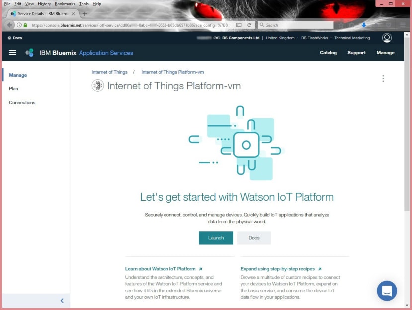
- In the sidebar menu, select Services->Internet of Things
- In the Internet of Things Platform window, click the Get Started button
- In the next window, click the ‘Create’ button
- In the window after that, click the ‘Launch’ button
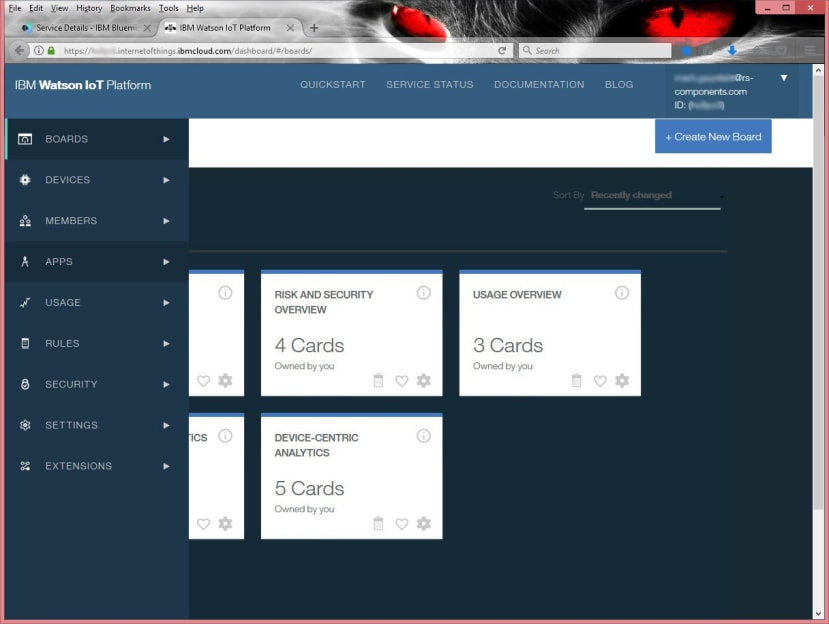
- When you get to the Dashboard window, use the sidebar menu to select ‘Apps’
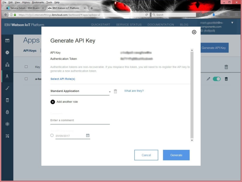
- In the Apps window, take note of your ID (in the upper right corner, under account)
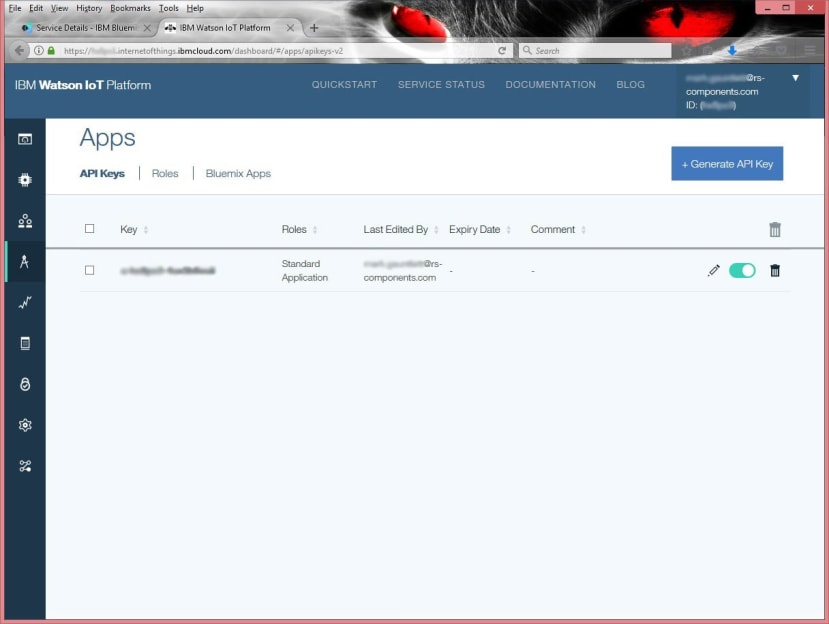
- Select the ‘+ Generate API Key’ button and take note of (or copy and paste into notepad) the API Key and Authentication Token
- Click the ‘Generate’ button
- Copy your key, token, and ID to the API_Key, Auth_Token, and Org_ID settings into the Electric Imp RefrigerationMonitor.agent code (near the end of the file). I show you exactly how to do this later under ‘Electric Imp Device and Agent’


Provisioning Your Imp Module
Otherwise known as connecting your Electric Imp to the Internet. Before you can do anything with your module, you will need to provide it with the information it needs to log into your wi-fi connection. This is done using the Electric Imp BlinkUp app, which you have (hopefully) already loaded onto your smartphone.
- Start the BlinkUp app on your device
- In the app, log into your Electric Imp developer account
- Enter your WIFI credentials
- Follow the instructions in the app to BlinkUp your device
This video also shows you how BlinkUp is done:
When BlinkUp is successful the LED on the Imp module will blink green and the app will show you the device’s unique ID, like this:
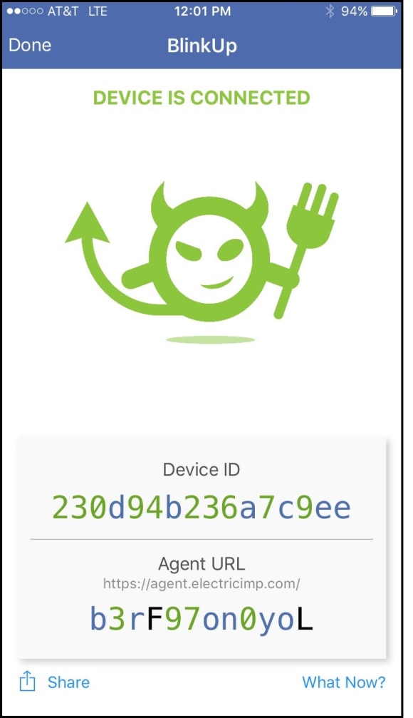
A fast flashing red LED tells you that the device wasn’t able to read the BlinkUp transmission and you will have to try again, perhaps with the phone closer to the module.
Electric Imp Device and Agent
You can find the complete source code for this example at:
https://github.com/electricimp/examples/tree
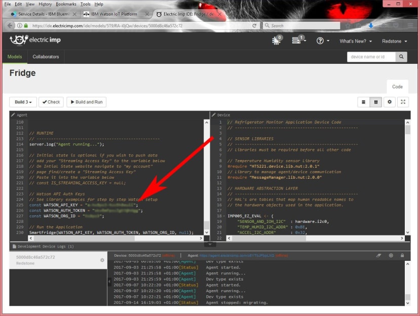
There are two files; one for the module and one for the ImpCloud agent. These need to be copied and pasted into the appropriate windows of the IDE:
- RefrigeratorMonitor.agent.nut -> IDE Agent Window (on the left)
- RefrigeratorMonitor.device.nut -> IDE Device Window (on the right)
The code is written in Squirrel which is another derivative of C/C++ and is similar to JavaScript. It is a high-level, imperative, object-oriented language with garbage collection. There are also Electric Imp Squirrel resources here. The application code is run on a virtual machine, both on the module and in the ImpCloud. This is another means of reducing the attack surface available to hackers.
However, to run this example we won’t need to learn any Squirrel. All we need right now is to remember to copy the Watson IoT authentication information into the bottom of Agent Code – highlighted in the image above.
Once this information is added, click the ‘Build & Run’ button. In the log, you should see something along the lines of:
[Device] sending readings
[Agent] Watson send successful
If you see something like: ‘Watson send error: Error: Invalid API Key or Authentication Method’
Then double-check your key, token, and org ID values. If the problem still persists, wait a few minutes and try again as sometimes Watson needs time the authentication to internally propagate.
Creating Watson Data Visualisations
We are now going to create our pretty graphs (and meters, should you want them) in our Watson environment.
In the Dashboard window sidebar menu, select Boards. Then click the '+ Create New Board' button.

Give the board a Name (e.g. Refrigerator Monitor) and a Description (optional). Then Click on Next and Submit. Now in the Dashboard window, click the Board you just created in the Your Boards section.

To create our Temperature Line Chart, click card type 'Line Chart'. Then:
- Select device Arrow_Imp005-EZ and click Next
- Click + Connect new data set
- As Event, select RefrigerationMonitor
- As Property, select data.0.temperature
- As Type, select ‘Number’. Click ‘Next’
- Select 'L' settings. Click ‘Next’
- Add Title and select ‘Color Scheme’. Click ‘Submit’
Repeat this process for a Humidity Line Chart. Similarly, you can create a Value Card for an ‘Open Door Alert’ by selecting data.0.doorOpen as the data source. For a Temperature Alert Value Card, select data.0.tempAlert as the data source.
When you are done, RefrigerationMonitor data should automatically start to be displayed in the dashboard.

Final Thoughts
I enjoyed using the Imp 005 module. I also liked the amount of thought Electric Imp have put into securing their IoT architecture. It is a major step in the right direction if IoT is ever going to become as ubiquitous as the tech prophets predict. Of course, Electric Imp’s solution won’t suit every application but for many situations, there is a lot to be said for offloading security and things like OTA updates to someone who specialises in that area and knows what they are doing.