How to Figure Out Non-Inverting Amplifiers and Inverting Amplifiers
Follow article
 Dave from DesignSpark
How do you feel about this article? Help us to provide better content for you.
Dave from DesignSpark
Thank you! Your feedback has been received.
Dave from DesignSpark
There was a problem submitting your feedback, please try again later.
Dave from DesignSpark
What do you think of this article?
Introduction
The electronic operational amplifier is a commonly used component in signal processing and signal conversion. There are two types of non-inverting input and inverting input in common. The typical circuit is as follows:

Figure 1. Simple Amplifying Circuit
Differences between Non-Inverting and Inverting Amplifiers
- Non-Inverting Amplifiers
1) The output is in phase with the input.
2) High input impedance
3) The Non-inverting output can be used for bootstrap.
4) The inverting input is idle and can be used for other purposes.
5) Often used as a voltage follower
6) Input voltage in series with negative feedback.
7) The input has no virtual ground, the common-mode voltage is large, and the anti-interference ability is poor.
- Inverting Amplifiers
1) The output and the input are reverse.
2) The amplifying circuit can use feedback compensation.
3) It can be used to increase the conversion rate.
4) Low signal source impedance, high signal-to-noise ratio
5) It can be used as a current input.
6) To reduce input impedance or maintain a certain value in the circuits
7) The Non-inverting input end is idle and can be used for other purposes.
Application and RC Circuit Analysis
For the non-inverting amplifier, since the feedback loop reaches the inverting end, its amplification factor has nothing to do with the input signal. Even if the internal resistance R of the input signal changes greatly, it will not affect the amplification factor of the op amp. But the inverting amplifier is affected by the internal resistance of the signal. However, the non-inverting amplifier also has certain inconveniences: If the zero adjustment is performed on the inverting terminal of the non-inverting op amp or an addition circuit is added, the impedance of the signal source will change to affect the gain. Generally, when using a non-inverting amplifier, the inverting end does not connect other circuits except for the feedback circuit.
A common application of non-inverting amplifiers is voltage followers, following is the voltage follower circuit:
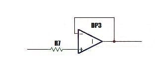
Figure 2. Voltage Follower Circuit
In this circuit, R7 is a protection resistor, which is used to prevent a large current from flowing into the clamp diode of the operational amplifier and burning the component. Generally, a phase compensation capacitor is required when using a non-inverting amplifier to make the system stable, usually a large phase compensation capacitor. So the voltage follower with a phase compensation capacitor is often used in the condition that the input signal rises slowly and the conversion rate is small. When processing signals with high rise speed and large amplitude, the emitter follower or FET source follower designed by transistors or a dedicated voltage follower operational amplifier are generally used.
When using a voltage follower, if self-oscillation occurs, the first thing that comes to mind is phase compensation. Reduce the electric shock by moving the pole position. As for the first method, the RC circuit is connected in series at the non-inverting and inverting ends of the operational amplifier, as follows:
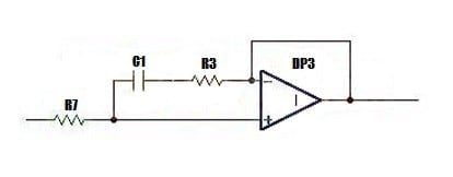
Figure 3. RC Circuit
Another method is to connect a resistor in series between the load and the voltage follower (the load behaves as a capacitor). At this time, it is necessary to confirm that if the load is non-capacitive through calculation, oscillation will not occur. In addition, the effect of this method is not very obvious because of amplifier oscillation.

Figure 4. RC Circuit
In the electronic circuit design, usually, the circuit becomes oscillating due to carelessness to the characteristics of the load. At this time, we should pay attention to the load.
Normally, when the load is capacitive and less than 2000pF, the oscillation can be eliminated by connecting a small resistor in series with the output of the load and the op amp. The resistor R2 is between 10-300Ω.

Figure 5. Amplifier Circuit
When the load is large, we use the following method to eliminate:

Figure 6. Amplifier Circuit
The compensation capacitor C2 and the feedback resistor R3 form an advanced compensation network, forming a new zero point, which offsets the new pole formed by the capacitive load Cl and the op amp output resistance R1, thus achieving the purpose of eliminating oscillation. At this time, the size of the compensation capacitor C2 is C2=Cl(R1+R2)/R3, and R2 takes a value of 10~300Ω.
When using a non-inverting amplifier, it is necessary to care about the voltage range. If the voltage exceeds the rated voltage of the op amp damage will be caused to the device, then the commonly used limiting circuit is required.

Figure 7. Non-inverting Amplifier Circuit
When the voltage signal is input through the resistor R15, the signal input to the non-inverting terminal of the operational amplifier may rise slowly due to the influence of the amplifier's own input capacitance and other stray capacitance. If this happens, the bootstrap circuit may also be used. At this time, connect a small capacitor C4 to compensate, the value of C4 is generally C4=(R14/R16)*C3
The C3 is the total capacitance at the input end. If the value of C4 is greater than C3, the circuit will oscillate, therefore, C4 mostly uses ceramic fine-tuning capacitors with good temperature characteristics, which is convenient for adjusting when observing the waveform.

Figure 8. RC Circuit
Although the non-inverting op amp has various limitations and inconveniences during use, its unique characteristics are still useful in some typical circuits.
Related Article: Comparison Between Non-Inverting and Inverting Amplifiers