Gesture controlled weather station
Follow project
 Dave from DesignSpark
How do you feel about this article? Help us to provide better content for you.
Dave from DesignSpark
Thank you! Your feedback has been received.
Dave from DesignSpark
There was a problem submitting your feedback, please try again later.
Dave from DesignSpark
What do you think of this article?
 Weather station which displays temperature and humidity data when requested by the relevant gesture input.
Parts list
| Qty | Product | Part number | |
|---|---|---|---|
| 1 | XinaBox OD01, OLED Display 128x64 OLED Display Module with SSD1306 | 174-3718 | |
| 1 | Wi-Fi Core (ESP8266) | 174-3701 | |
| 1 | XinaBox SW01, Advanced Weather Sensor Module for BME280 | 174-3744 | |
| 1 | Gesture (APDS-9960) | 174-3739 | |
| 1 | XinaBox, USB Programming Interface Module for FT232R, IP01 | 174-3703 | |
| 1 | AVX SMT OPEN ENDED CARD EDGE 10W | 174-4977 | |
This project was built with XinaBox ☒CHIPS and Arduino IDE. It is a 5 min project, that allows you to view data received from the ☒SW01 on the OLED screen of the ☒OD01 when gestures are registered by the ☒SL06. Using the ☒CHIPS assembly is easy. Creating the code for this project is easy with the Arduino IDE software. The code for this project works with 3 ☒CHIP cores. For this project, we've chosen to show you how it works with the☒CW01.
Step 1: Downloading the Libraries
- Go to Github.xinabox
- Download xCore ZIP
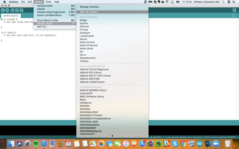
- Install xCore ZIP into the Arduino IDE by selecting "Sketch", "Include Library", then "Add.ZIP Library", as seen below.
- Download xSW01 ZIP
- Add this library in the same way as you did above for the xCore.
- Repeat for the xOD01 ZIP and xSL06 ZIP
Step 2: Programming
- Connect the IP01 and CW01 together using an ☒BUS Connector. Make sure the ☒CHIPS' names are orientated the same way.
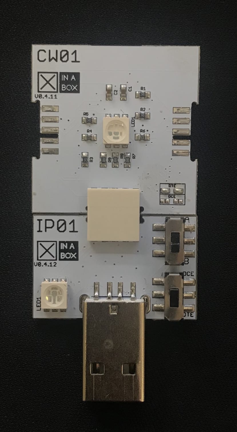
- Insert into an available USB port.
- Download the zip file from GitHub here and open with your Arduino IDE. Alternatively, you could create your own code to achieve the same objective using the relevant principles.
- Compile the code to ensure there are no errors.
- After successfully compiling to ensure no errors are found, you may upload the code to your ☒CHIPS.
- If you're using the CW01 with a MacBook you could download the xFlasher and then upload the bin file from the XinaBox Samples page - Gesture Weather
Step 3: Final assembly
- Once uploaded successfully, you can remove the IP01 from the USB port.
- Disconnect the CW01 from the IP01.
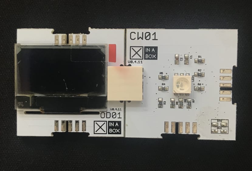
- Connect the CW01 to the OD01 as shown below.
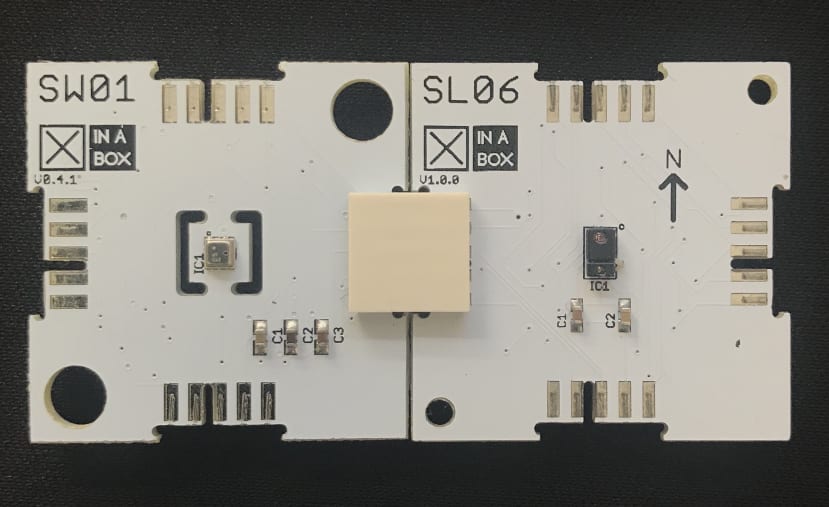
- Next, connect the SW01 to the SL06 as seen below.
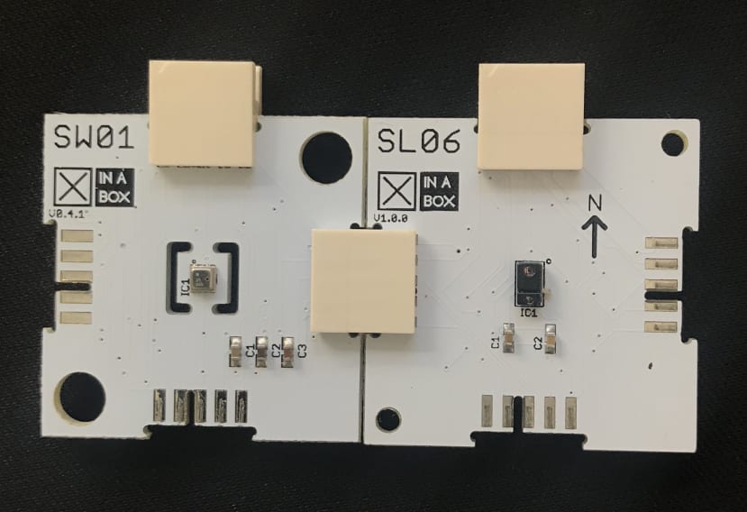
- Attach 2 connectors as seen below
- Now connect the two horizontal panels you created and attach the IP01 to the bottom as seen below.
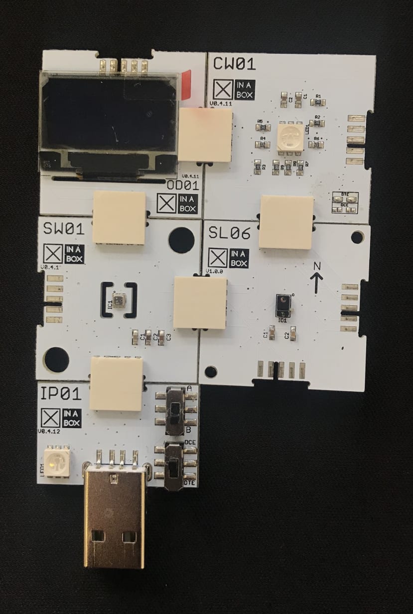
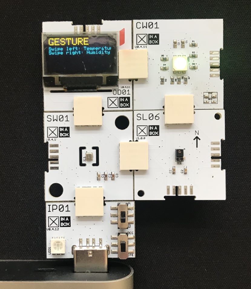
- Insert your new board into the USB port. Your OLED screen should now look just like the image shown below.

- Remove the board from the USB port again.
- Insert IP01 into USB power, for example, a power bank
- Your board is now portable. Happy experimenting!